1. 서 론
2. 수압파쇄를 이용한 수압파쇄를 현지응력측정 이론
3. 수압파쇄를 이용한 현지응력측정법의 신뢰도 제고 방안
3.1 균열재개압력(fracture reopening pressure)의 재정의
3.2 수압파쇄시스템의 컴플라이언스(compliance) 향상
3.3 수압파쇄시스템 컴플라이언스 차이에 따른 데이터 품질
4. 결 론
1. 서 론
현지응력 혹은 초기응력은 자연상태에서의 암반에 존재하는 응력을 의미하는 것으로 ‘초기지압’으로도 표현된다. 초기응력은 주로 광산 및 토목분야에서 사용되는 용어로 암반에 갱도 및 터널 등의 지하구조물을 굴착하기 전 평형상태를 나타낸다. 지하구조물의 굴착 후에는 ‘유도응력’ 또는 ‘2차 응력’의 용어를 사용하여 갱도 및 터널 굴착에 따른 응력 변화를 표현하는데 유도응력은 구조물의 형태 및 사양뿐만 아니라 굴착 전 초기응력의 크기 및 방향에 의해 결정되므로 초기응력을 정확하게 파악하는 것은 지하구조물의 안전성 평가에 매우 중요한 요소라 할 수 있다.
초기응력 측정법은 크게 원위치시험과 실내시험으로 구분할 수 있다. 원위치시험으로는 수압파쇄법과 응력해방법이 대표적이며 실내시험은 시추코어를 이용한 AE법, 변형률변화법, DSCA법, ASR법 등이 제안되어 왔다. 또한, 적용 원리에 따라 초기응력 측정법을 분류하면 암석/암반의 파쇄를 이용한 방법, 응력해방에 의한 방법, 공벽 및 암석코어의 시추과정에서의 자연파괴를 이용한 방법과 시추코어를 이용하는 방법으로 분류할 수 있다. Table 1은 초기응력 측정법의 적용 원리에 따른 분류 및 측정법을 정리한 것이다.
Table 1.
Principles and classification of in-situ stress measurement methods (modified from Yokoyama, 2017)
|
Principles
|
Method
|
Features
|
References
|
Borehole
fracturing
|
Hydraulic
fracturing
|
Measuring water pressure changes and
injection
flow rate with artificial
fractures reopening
or closing
| Hubbert and Willis (1957),
Scheidegger (1962),
Kehle (1964),
Fairhurst (1964),
Haimson (1978),
Cornet (1986),
Mizuta et al. (1987),
Ito et al. (1999) |
|
Sleeve fracturing
|
Measuring sleeve pressure changes and
deformation of borehole with
artificial fractures
reopening
or closing
| Stephansson (1983),
Serata and Kikuchi (1986),
Sugawara et al. (1987),
Mizuta et al. (1988) |
|
Borehole-jack fracturing
|
Measure jacking pressure changes and
deformation of borehole with
artificial fractures
opening
or closing
| De la Cruz (1977),
Yokoyama and Nakanishi (1997),
Sano et al. (2007),
Yokoyama et al. (2010) |
Stress relief by
overcoring
|
Compact conical-ended
borehole overcoring
(CCBO)
|
Measuring strain on the conical end of
borehole
by using strain cell with
overcoring
| Oka et al. (1979),
Sugawara and Obara (1986),
Obara and Sugawara (1990),
Kobayashi et al. (1990),
Sakaguchi et al. (1992) |
Multi-axial strain gauge
(CRIEPI)
|
Measuring deformation of the borehole
diameter
by using multi-axial strain gauge
with overcoring
| Kanagawa et al. (1975),
Kanagawa et al. (1983) |
Borehole wall strain
(CSIRO)
|
Measuring strain on the wall of borehole
by using
HI cell with
overcoring
| Leeman (1968),
Hiramatsu and Oka (1968),
Pine et al. (1983) |
Borehole deformation
(USBM)
|
Measuring deformation of the borehole
diameter
by using three-component
USBM gauge with
overcoring
| Leeman (1959),
Obert et al. (1962),
Merrill (1967),
Sugawara et al. (1999) |
Borehole/
cores
breaking
|
Borehole breakout
(BBO)
|
Observing the compressed spalling of the
borehole wall by using borehole camera or
televiewer after drilling
| Leeman (1964),
Zoback et al. (1985),
Hickman et al.(1985) ,
Plumb and Cox (1987),
Cowtgill et al. (1993) |
Drilling induced fracturing
(DIF)
|
Observing the tension fractures of the
borehole wall
by using borehole
camera or FMI after drilling
| Stock et al. (1985),
Okabe et al. (1996),
Zoback et al. (2003) |
Core disking
(CD)
|
Observing the shape of disking core
by using core
scanner for core sample
| Sugawara et al. (1978),
Haimson and Lee (1995),
Ishida and Saito (1995),
Matsuki et al. (1997),
Yokoyama (2012) |
|
Core-based
|
Acoustic emission
(AE)
|
Monitoring the Kaiser effect of acoustic
emission
with loading onto core sample
| Kaiser (1953),
Kanagawa et al. (1977),
Seto et al. (1990) |
Deformation rate analysis
(DRA)
|
Monitoring the change of deformation
rate with
cyclic loading onto core sample
| Yamamoto (2000),
Yokoyama and Tanaka (1989) |
Differential strain curve analysis
(DSCA)
|
Monitoring the change of strain curve
of the core
sample under
the confining pressure
| Simmons et al. (1974),
Siegfried and Simmons (1978),
Strickland and Fen (1980),
Matsuki (1989) |
Anelastic strain recovery
(ASR)
|
Monitoring the change of strain of the
core
sample immediately after
drilling
| Voight (1968),
Teufel (1983),
Wolter
and Berckhermer (1989),
Matsuki (1991),
Matsuki and Takeuchi (1993) |
공학분야의 제품 및 신기술의 국제규격을 결정하는 국제표준화단체로서 가장 규모가 큰 조직으로는 국제표준화기구(International Organization for Standardization, ISO) 및 유럽표준화위원회(Comité Européen de Normalisation, CEN)가 있다. 특히 CEN의 기술위원회가 표준화한 규격인 EURO CODE는 2010년 이후 유럽연합 국가를 중심으로 한 설계기준으로 채택되어 전 세계적으로 막대한 영향을 미치고 있다. 다만, Table 2에 소개된 초기응력측정과 관련한 규격은 ISO 및 CEN에서는 규정되어 있지 않고 ASTM (American Society for Testing and Materials, 미국재료시험협회) 및 BS(British Standards)에 일부 관련 내용이 규정되어 있다.
현지응력측정과 관련한 주요 기준 및 시험법은 국제암반역학회(International Society for Rock Mechanics and Rock Engineering, ISRM)의 시험분과기술위원회가 발간하는 제안시험법(Suggested Method)에 규정되어 있다. 다만, Table에 소개된 현지응력측정법 중 수압파쇄법과 응력해방에 의한 방법에 대해서만 세부 규정이 수록되어 있고 나머지 측정법에 대해서는 표준화된 방법이 수립되어 있지 않거나 현재까지 진행 중에 있다. ISRM 제안시험법에 수록된 현지응력측정 관련 규정은 1987년 제정 이래 1999년 및 2003년 개정된 것이 최신판이며 일본에서는 일본지반공학회(Japanese Geotechnical Society, JGC)가 2012년 현지응력측정 관련 규정을 발행한 바 있다. 국내에는 2016년 한국암반공학회 시험분과위원회가 제정한 ‘현지암반응력 결정을 위한 수압파쇄 표준시험법(KSRM, 2016)’이 있다. Table 2는 현지응력측정법과 관련한 표준화 규격 및 관련기준을 요약한 것이다.
Table 2.
Standard and suggested methods of in-situ stress measurements (Yokoyama, 2017)
|
Organization
|
Category
|
No./Author
|
Title of standard
|
Issued year
|
|
ASTM
|
Hydraulic fracturing
|
D4645-08
|
Standard Test Method for Determination of In-Situ
Stress in Rock
Using Hydraulic
Fracturing Method
|
2008
|
Overcoring
(USBM)
|
D4623-08
|
Standard Test Method for Determination of In Situ
Stress in Rock
Mass by Overcoring Method-
USBM Borehole Deformation Gauge
|
2008
|
|
BS
|
Hydraulic fracturing
|
BS5930
|
30.2.6 Hydraulic fracturing technique
|
1999
|
|
Overcoring
(CSIRO/ Borre probe)
|
BS5930
|
30.2.2 Determination of the in-situ
triaxial state of stress in rock
|
1999
|
|
ISRM
|
Hydraulic fracturing
|
Haimson B.C. and
Cornet F.H.
|
ISRM Suggested Methods for rock stress
estimation—Part 3: hydraulic fracturing
(HF) and/or hydraulic testing
of pre-existing fractures (HTPF)
|
2003
|
Overcoring
(Borre probe)
|
Sjöberg J.,
Christiansson J.,
Hudson A.
|
ISRM Suggested Method for rock stress
estimation-Part 2:
overcoring
methods
|
2003
|
Overcoring
(CCBO)
|
Sugawara K. and
Obara Y.
|
Draft ISRM suggested method for in situ stress
measurement using the compact conical
-ended borehole overcoring
(CCBO) technique.
|
1999
|
Overcoring
(USBM)
|
Commission on
testing methods
|
Suggested Method for Rock
Stress Determination
|
1987
|
Overcoring
(CSIR/CSIRO)
|
Commission on
testing methods
|
Suggested Method for Rock
Stress Determination
|
1987
|
|
JGS
|
Overcoring
(CRIEPI)
|
JGS3741-2012
|
Method for initial stress measurement
by overcoring technique using
multi-axial strain gauge
|
2012
|
Overcoring
(CCBO)
|
JGS3751-2012
|
Method for initial stress measurement
by compact conical-ended
borehole overcoring technique
|
2012
|
2. 수압파쇄를 이용한 수압파쇄를 현지응력측정 이론
수압파쇄를 이용한 현지응력측정은 시추공 내 일정 구간에 수압을 가하여 인위적으로 조성한 암반 균열이 생성, 폐쇄(closure), 재개(reopening)되는 시점의 수압 변화로부터 암반에 작용하고 있는 응력을 산정하는 원리이다. 암반은 등방균질탄성체(isotropic homogeneous elastic body)로 가정하며 수직 시추공에 직교하는 2차원 수평면에서의 응력상태는 Fig. 1과 같이 최대주응력(SH)과 최소주응력(Sh)을 이용하여 나타낸다. 또한, 시추공 방향과 평행한 방향(일반적으로 수직 방향)의 응력(Sv)은 시험구간 상부의 단위중량(밀도)과 심도의 함수로 계산할 수 있으며 SH, Sh, Sv는 모두 주응력(principal stress)에 해당한다.
Fig. 1의 SH 방향과 교차하는 공벽 A점에서의 응력(σθ1) 및 Sh 방향과 교차하는 공벽 B점에서의 응력(σθ2)는 각각 식 (1)과 식 (2)와 같이 표현된다.
압축응력을 (+)라 하면, σθ A < σθ B이므로 시추공 내 수압 P를 증가시킴에 따라 인장응력(-)이 최대가 되는 A점에서 SH에 평행한 방향(; Sh에 수직한 방향)으로 인장균열이 형성된다. 인장균열이 형성되는 시점의 수압(Pb)를 파쇄압(breakdown pressure)이라 하며 암반의 인장강도(T)와 공극수압(Pp)을 이용하여 식 (3)과 같이 표현할 수 있다.
균열 생성이 확인되면 시추공 내 물 주입을 중지하고 송수관 밸브를 해방시켜 수압을 강하시키고 생성된 균열은 닫히게 된다. 균열이 완전히 닫힌 후 다시 수압을 증가시키면 균열은 벌어지고 이때의 수압(Pr)을 균열재개압력(re-opening pressure)이라 하여 식 (4)와 같이 표현된다.
식 (4)로부터 균열재개 시, 수압파쇄를 통해 형성된 균열은 완전히 닫혔다가 벌어지는 것으로 가정하며 이 경우 균열의 인장강도(T)는 소멸되어 사라지고(즉, T = 0), 주변 암반 내 공극수압(Pp)은 균열이 생성되기 전 공극수압과 동일하다.
수압파쇄로 생성된 균열이 충분히 진전된 후 물 주입을 순간적으로 중지(shut-in)하면 균열 내 수압이 감소하기 시작하여 균열면에 수직으로 작용하는 Sh와 평형을 이루는 시점에 균열은 닫히고 이 때의 압력에 해당하는 균열폐쇄압(shut-in pressure, Ps)을 식 (5)와 같이 결정할 수 있다.
따라서, 최소수평주응력(Sh)은 균열폐쇄압력(Ps)을 측정하여 결정할 수 있고, 최대수평주응력(SH)은 식 (4)의 균열재개압력(Pr)을 이용하여 계산한다. 나머지 수직방향 주응력(Sv)은 시험구간 상부암반의 단위중량(γ) 또는 밀도(ρ)와 중력가속도(g)를 이용하여 식 (6)과 같이 계산된다.
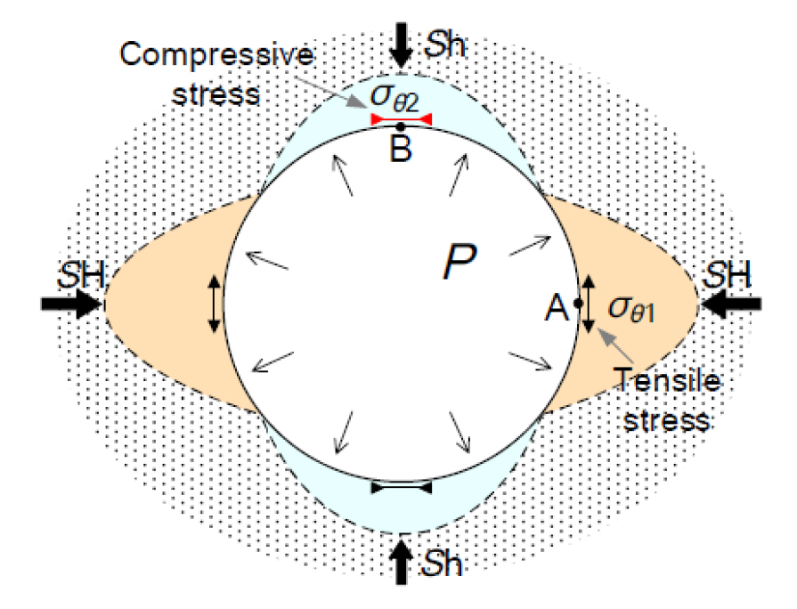
Fig. 1.
In-situ stresses condition on the 2-dimensional plane perpendicular to the vertical borehole during hydraulic fracturing
3. 수압파쇄를 이용한 현지응력측정법의 신뢰도 제고 방안
3.1 균열재개압력(fracture reopening pressure)의 재정의
Fig. 2은 기존의 연구를 통해 파악된 균열폐쇄압력(Ps)과 균열재개압력(Pr)을 비교한 것으로 두 압력이 매우 유사한 값을 보임을 알 수 있다. 이 경우, 균열폐쇄압력은 최소주응력과 동일하고(식 (5)) 동시에 균열재개압력(식 (4))과 같은 값을 가져야 하므로 식 (4)와 식 (5)를 동시에 만족시킬 수 없는 오류가 발생한다.
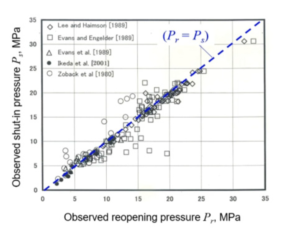
Fig. 2.
일본지반공학회에서는 수압파쇄에 의해 형성된 균열은 균열면의 거칠기로 인해 shut-in 이후 완전히 닫히지 않고 잔류 간극(residual aperture)이 존재하기 때문에 균열 내 수압은 초기 공극수압(Pp)이 아닌 시추공 압력과 동일한 값을 가지는 것으로 간주하였다(Fig. 3). 따라서, 식 (4)에서 균열재개압력 계산을 위한 균열 내 압력을 공극수압(Pp)을 시추공 내 압력(Pr)로 대체하고 균열재개압력(Pr)을 식 (7)과 같이 새롭게 정의하였다. 이는 기존 접근법에서 균열 재개가 최소주응력과 동등한 수준에서 발생한다는 사실과 달리 최소주응력보다 낮은 압력에서 발생함을 의미한다.
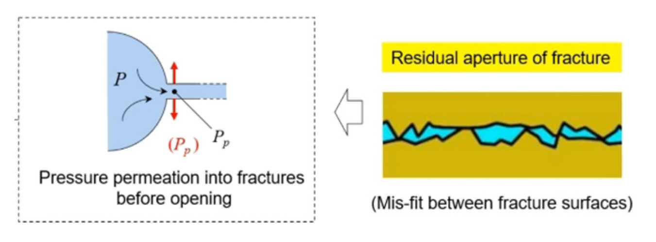
Fig. 3.
New fracture reopening pressure considering induced tensile fracture surface roughness and mismatch (modified from Ito and Yokoyama, 2021)
3.2 수압파쇄시스템의 컴플라이언스(compliance) 향상
수압파쇄를 통해 산정하는 최소주응력(Sh)은 균열폐쇄압력(Ps)과 같으며 균열폐쇄압력은 shut-in 이후 압력하강곡선으로부터 구하는 방법이 가장 보편적이며 신뢰성이 높은 것으로 알려져 있다. 그러나, 최대주응력(SH)은 균열폐쇄압력외에 균열재개압력(Pr)에 대한 정보를 추가로 필요로 하고 균열재개압력은 수압파쇄시스템의 컴플라이언스(compliance)에 크게 영향을 받는 것으로 보고된 바 있다(Ito et al., 1999). 수압파쇄시스템의 컴플라이언스는 주입량과 압력변화의 관계의 직선 기울기로 정의되고 시스템의 컴플라이언스가 낮을수록 강성(stiffness)이 증가하여 주입량 변화에 따른 압력변화(즉, 균열폐쇄압력)를 보다 정밀하게 관측할 수 있다. 수압파쇄 시스템의 강성도 제고를 위해서는 가능한 가압시스템의 체적을 최소화하고 사용되는 배관 등은 강성 재료로 제작되어야 한다. 기존의 수압파쇄시스템을 개량하여 시스템 강성을 향상시킨 사례로 송수관으로 강성의 스테인레스관을 사용하고 송수 펌프에 실린지펌프를 채택한 사례(Fig. 4)와 시추공 바닥에 소구경의 수압파쇄용 시추공을 추가 굴착하여 시스템 체적을 감소시킨 사례(BABHY, Fig. 5)가 보고되었다. 각각의 수압파쇄시스템의 적용 조건 및 사양을 함께 수록하였다. Fig. 6은 BABHY 시스템을 이용하여 기존 시추공 하단에 수압파쇄용 소구경 시추공을 추가 굴착한 후 전용 시스템을 투입하여 수압파쇄를 실시하고 기존 시추를 진행하는 순서도를 나타낸다.
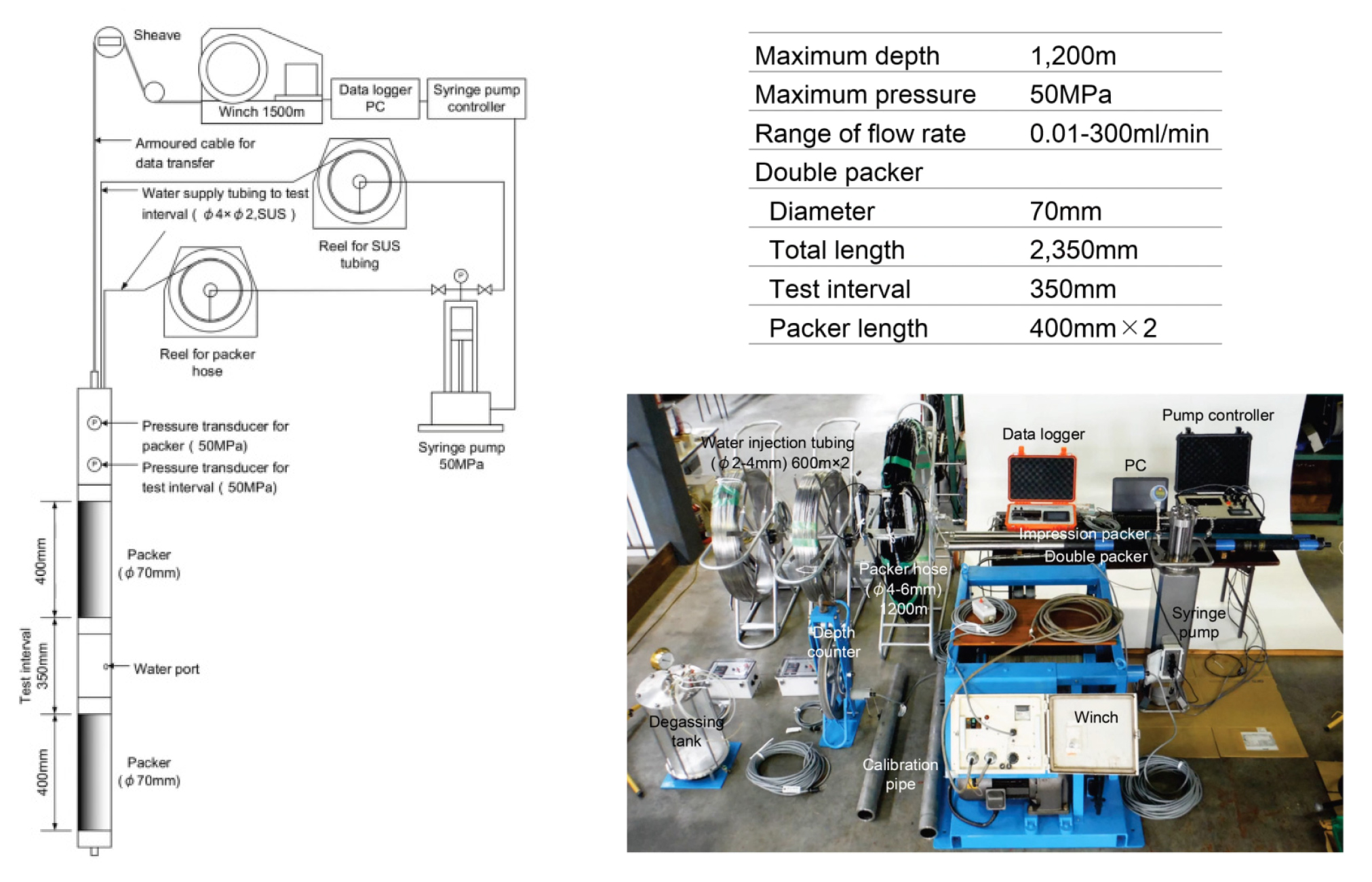
Fig. 4.
Hydraulic fracture system with high stiffness syringe pump and the water supply pipe and its specification (modified from Yokoyama et al., 2021)
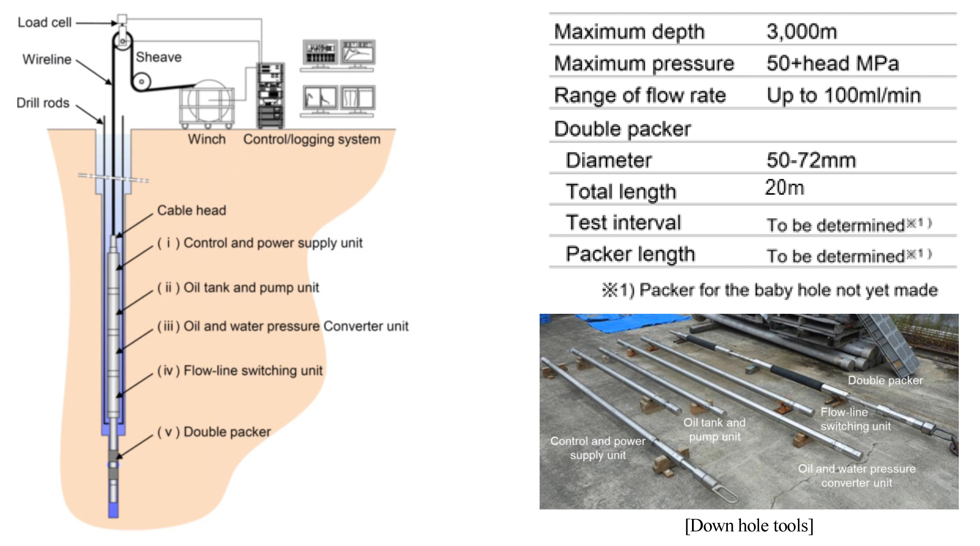
Fig. 5.
Hydraulic fracturing system (Baby Borehole Hydraulic Fracturing, BABHY) with downhole pump in the double packer (modified from Yokoyama et al., 2021)
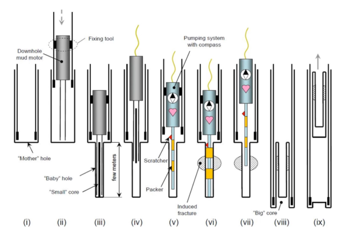
Fig. 6.
Fig. 7은 시스템 컴플라이언스 성능을 향상시킨 수압파쇄시스템을 이용하여 획득한 유량-압력변화의 시간경과 데이터를 표시한 것이다. 시험 데이터로부터 10~20 ml/min전후의 매우 미세한 유량을 고압으로 제어가능함을 확인할 수 있을 뿐만 아니라 주입개시와 동시에 압력이 민감하게 변화함을 관측할 수 있다. Fig. 8은 주입 후 압력상승 구간에서의 균열재개압력 (a) 및 shut-in 구간에서의 균열폐쇄압력 (b)를 결정하는 그래프이다. 균열재개압력은 압력-주입량 관계의 극점에 해당하고 균열폐쇄압력은 shut-in 후 압력변화의 최초 변곡점으로부터 얻어진다.
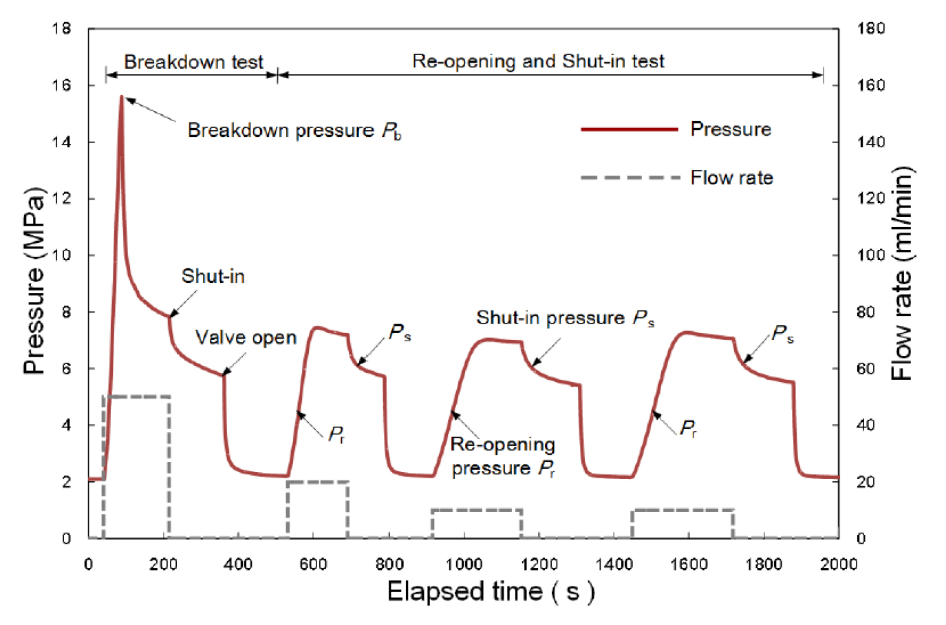
Fig. 7.
Measured pressure and flow rate during the hydraulic fracturing test using less compliant and high stiffness system (Yokoyama et al., 2021)
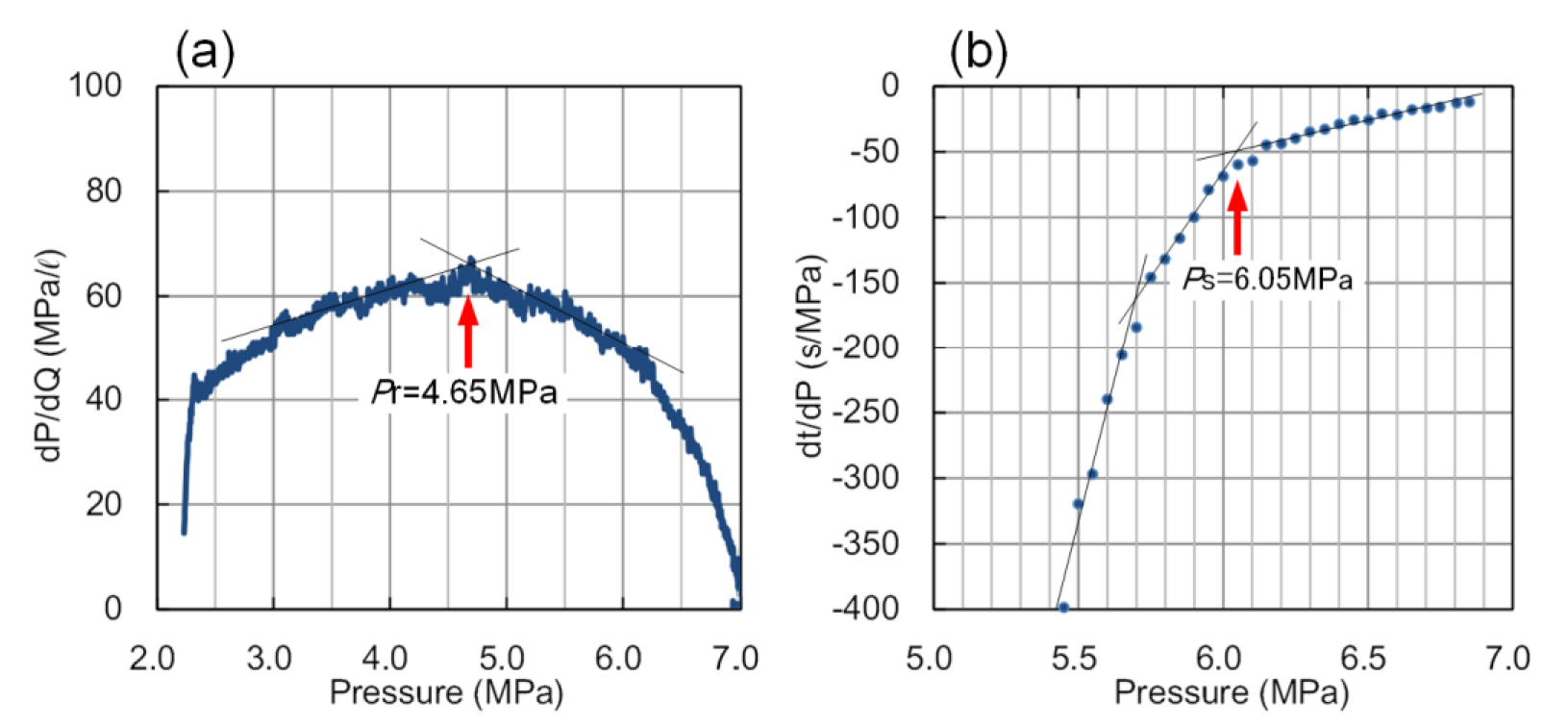
Fig. 8.
Fig. 9은 시스템 컴플라이언스가 균열재개압력 결정에 미치는 영향을 나타낸 것이다. 일본의 카마이시(Kamaishi) 광산 부지의 300 m 심도에서 동일한 균열을 대상으로 서로 다른 컴플라이언스 특성을 가지는 시스템을 사용하여 현장실험을 실시하였다(Ito et al., 2005, 2006). 두 시스템의 차이는 사용된 튜브의 길이(체적) 및 재질의 강성도 차이로 시스템 컴플라이언스(C0)는 각각 1.6 cc/MPa 및 41.2 cc/MPa로 약 20배의 차이를 보인다. 그림에서 시스템 강성이 클수록 주입 유랑 증가에 따른 즉각적인 압력 변화 거동을 확인할 수 있다. 반면에 기존 시스템의 경우 완만한 압력 상승 거동을 보였다. 유량-압력 거동의 직선 구간을 벗어나는 지점에 해당하는 균열재개압력은 고강성 시스템에서 약 6 MPa, 기존 시스템의 경우 약 9 MPa로 결정되어 두 시스템 간의 차이가 약 3 MPa까지 발생함을 확인할 수 있다.
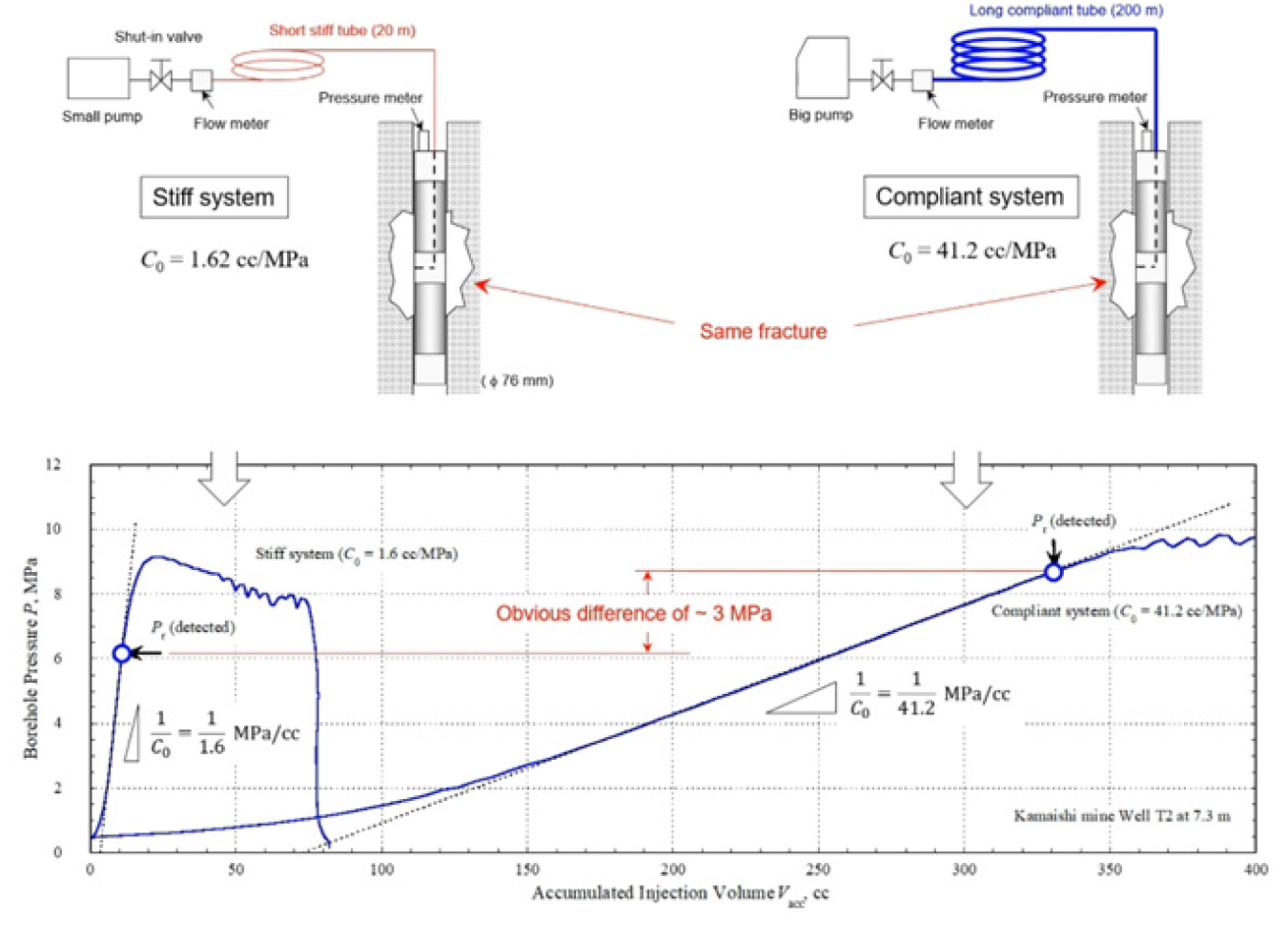
Fig. 9.
Comparison of pressure responses during hydraulic fracturing and fracture reopening pressures between stiff and compliant system (Ito and Yokoyama, 2021)
수압파쇄시스템 컴플라이언스는 주입 유량과 시추공 내 압력변화의 관계로 수압에 의해 시험구간 내 균열 생성 이후에는 그 특성이 달라질 것으로 예상된다. 따라서, 시스템의 컴플라이언스는 균열 생성 전후로 다음과 같이 정의할 수 있다.
Fig. 10은 균열 재개(re-opening) 전후의 균열의 변형과 유량-압력 변화를 함께 도시한 것이다. 가압 초기 균열은 여전히 닫혀 있는 상태로 압력이 증가함에 따라 균열이 열리기 시작하여 초기 직선 구간에서 벗어나는 균열재개압력에 해당하는 압력(그림의 “True”)을 보인다. 그러나, 균열 진전은 응력집중구간(stress concentration region, SCR) 내부에 국한되어 균열의 체적증가가 시스템 컴플라이언스에 미치는 영향은 크지 않다. 균열 내부 압력이 지속적으로 상승되면 균열의 진전에 따른 체적 증가로 시스템 컴플라이언스는 커지고 압력변화가 급격히 관측되는 지점(그림의 “Detected”)의 압력을 일반적으로 균열재개압력으로 결정하게 된다. 이와 같은 이유로 기존의 실험결과에서 균열폐쇄압력이 균열재계압력과 매우 유사한 값을 보이는 것을 설명할 수 있다(Fig. 2). 따라서, 균열재개압력의 정밀도 높은 관측을 위해서는 시스템 컴플라이언스를 가능한 낮게 구성하여 균열의 열림에 따른 압력변화를 신속하게 감지할 수 있도록 해야 한다.
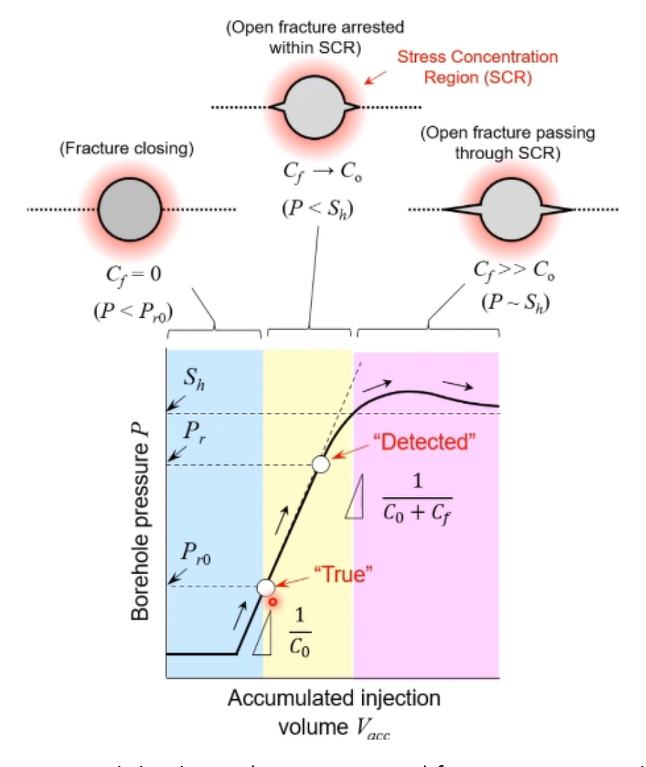
Fig. 10.
Fig. 11과 같은 조건에서의 균열재개압력 결정을 위한 적정 시스템 컴플라이언스는 최대(SH) 및 최소주응력(Sh), 시추공 반경(a), 균열 높이(h), 암반의 탄성계수(E), 포아송비(ν)등의 영향을 받는다. 균열높이(h)가 일정한 경우 KGD 균열 모델(Geertsma and Klerk, 1969)을 적용하여 시스템 컴플라이언스는 다음과 같이 정의할 수 있다(Ito et al., 1999).
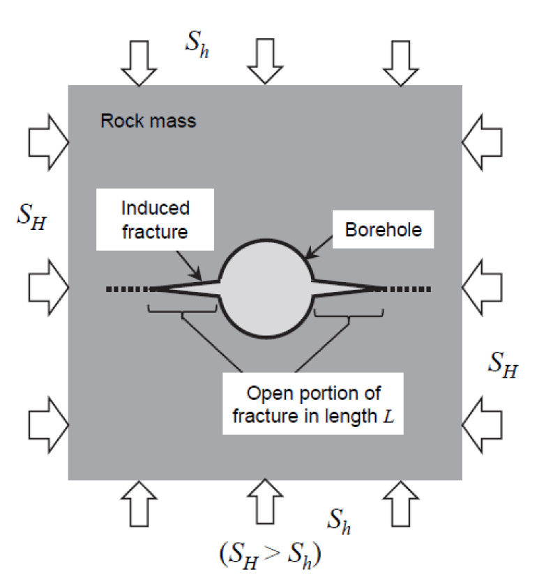
Fig. 11.
여기서, 균열길이(L), 수압(P), 최대 및 최소주응력은 다음의 관계를 만족시킨다.
식 (8)의 적분식은 다음과 같이 표현되며 Fig. 12의 순서도와 같은 반복 과정을 거쳐 계산할 수 있다.
여기서, 시추공 내 수압(P)의 초기값은 공극수압(Pp)과 동일하고 최소주응력(Sh)보다는 작은 것으로 가정한다.
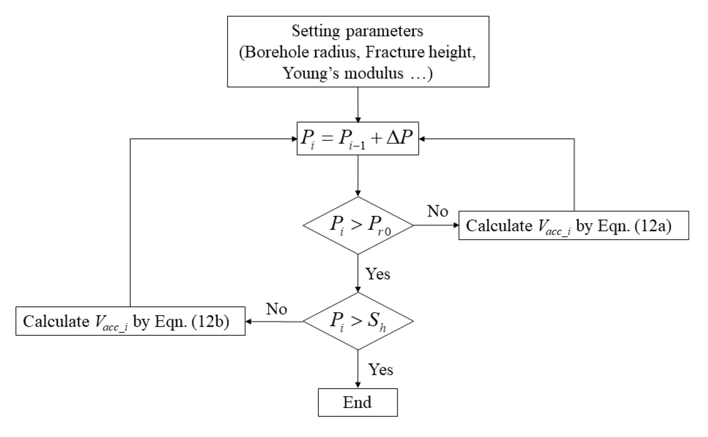
Fig. 12.
Fig. 13 및 Table 4은 위와 같은 방식으로 수압파쇄시스템 컴플라이언스와 시추공 주변 암반의 탄성계수에 따른 균열재개압력 계산결과를 비교한 것이다. 계산에 이용한 제반 조건은 Table 3에 요약하였다. Fig. 13에서 균열재개압력의 정해(true solution)는 5 MPa이나 표에서는 시스템 컴플라이언스와 탄성계수의 상대적 대소 관계에 따라 매우 상이한 균열재개압력이 계산됨을 확인할 수 있다. 시스템 컴플라이언스와 탄성계수가 커질수록 균열재개압력의 계산 결과가 정해(5 MPa)로부터 점점 멀어져 최소주응력에(즉, 균열폐쇄압력)해당하는 10 MPa에 근접하는 결과에 해당한다. 이로부터 주변 암반의 탄성계수가 10, 5, 2, 1 GPa 조건에서 오차 범위 30% 이내로(Table 4의 빗금 칸) 균열재개압력을 산출하기 위한 시스템 컴플라이언스는 5, 10, 20, 50 cc/MPa보다 작아하고 주변 암반의 탄성계수가 클수록(즉, 강성일수록) 수압파쇄시스템의 컴플라이언스가 충분히 낮아야(즉, 강성도가 충분이 높아야) 초기응력 계산결과의 신뢰도가 확보됨을 알 수 있다.
Table 3.
Assumed parameters for the calculation of fracture re-opening pressure at different compliance and Young’s modulus conditions
|
Parameters
|
Unit
|
Values
|
|
System compliance (C0)
|
cc/MPa
|
2, 10, 50
|
|
Borehole radius
|
m
|
0.05
|
|
Fracture height
|
m
|
1 (assuming constant)
|
|
Young’s modulus of rock
|
GPa
|
10
|
|
Poisson’s ratio of rock
|
-
|
0.2
|
|
(initial) Pore pressure
|
MPa
|
3
|
|
Assumed maximum stress (SH)
|
MPa
|
20
|
|
Assumed minimum stress (Sh)
|
MPa
|
10
|
|
Step increment of P (not matter)
|
MPa
|
0.2
|
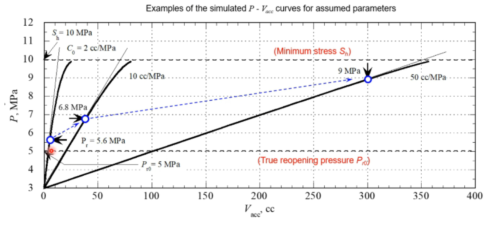
Fig. 13.
Table ?.
Results of calculated fracture re-opening pressures under different system compliances and Young’s modulus of rock (modified from Ito and Yokoyama, 2021)
|
E [GPa]
|
C0 [cc/MPa]
|
|
2
|
5
|
10
|
20
|
50
|
100
|
|
1
|
5.4
|
5.4
|
5.4
|
5.6
|
6.2
|
6.8
|
|
2
|
5.4
|
5.4
|
5.6
|
6
|
6.8
|
7.6
|
|
5
|
5.4
|
5.8
|
6.2
|
6.8
|
8
|
9
|
|
10
|
5.6*
|
6.2
|
6.8*
|
7.6
|
9*
|
9.8
|
3.3 수압파쇄시스템 컴플라이언스 차이에 따른 데이터 품질
Fig. 14 및 15는 시스템 컴플라이언스 차이가 수압파쇄시험 결과로 얻어지는 압력 및 유량 데이터에 미치는 영향을 현장실험을 통해 파악한 결과로 균열폐쇄압력과 균열재계압력을 비교한 것이다. 현장실험은 일본 미즈나미 지하연구시설(MIU) 부지 내 4 개의 시추공(AN-1, MIU-2, MIU-3, MIZ-1)을 이용하여 실시하였다. AN-1, MIU-2, MIU-3 시추공에서는 기존의 수압파쇄시스템을 이용하여 실험을 실시하였고 MIZ-1공에서는 고강성의 시스템을 사용하였다. Fig. 16은 기존 시스템으로부터 얻어진 시험결과 데이터를 도시한 것으로 유량 데이터의 분산이 매우 크고 압력변동 거동으로부터 균열재개압력을 명확하게 도출하기 어려움을 확인할 수 있다. 반편, 고강성 시스템을 이용한 시험결과에서는 압력-유량 그래프에서 초기 비선형 구간을 제외하고 선형에서 비선형 변화의 개시 시점을 명확하게 파악할 수 있음을 확인할 수 있다.
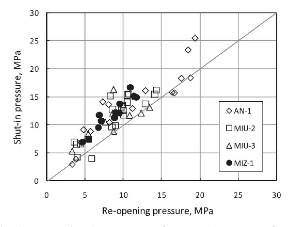
Fig. 14.
고강성의 시스템을 이용한 실험결과에서 균열폐쇄압력과 균열재개압력의 비(ratio)는 평균 1.4로 기존 시스템을 이용한 결과인 1.3보다 높은 값을 보였다. 또한, 일반적으로 균열폐쇄압력은 균열재개압력보다 큰 값을 보이는 것으로 알려져 있으나 반대의 결과(shut-in pressure / re-opening pressure < 1.0)를 보이는 데이터 오류(기존 시스템에 의한 관측건수 45건 중 10건에서 이러한 결과를 보임)가 관측되지 않은 점으로부터 고강성 수압파쇄시스템의 유효성을 확인할 수 있었다.
본 사례에서는 이러한 데이터 오류의 원인으로 기존 시스템으로부터 얻어진 유량 데이터의 분산이 매우 크고 압력변동 거동으로부터 균열재개압력을 명확하게 도출하기 어려움을 그림에서 확인할 수 있다. 반면, 고강성 시스템을 이용한 시험결과에서는 압력-유량 그래프에서 초기 비선형 구간을 제외하고 선형에서 비선형 변화의 개시 시점을 명확하게 파악할 수 있었다.
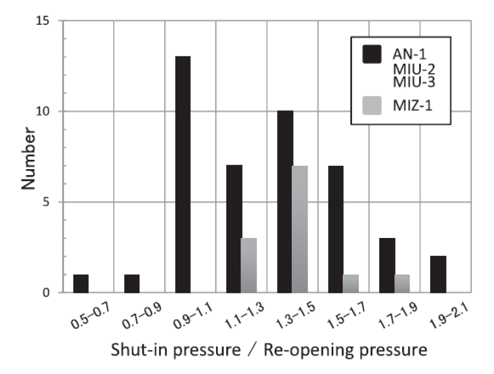
Fig. 15.
Histogram of the ratio between shut-in pressure and re-opening pressure (Sato et al., 2012)
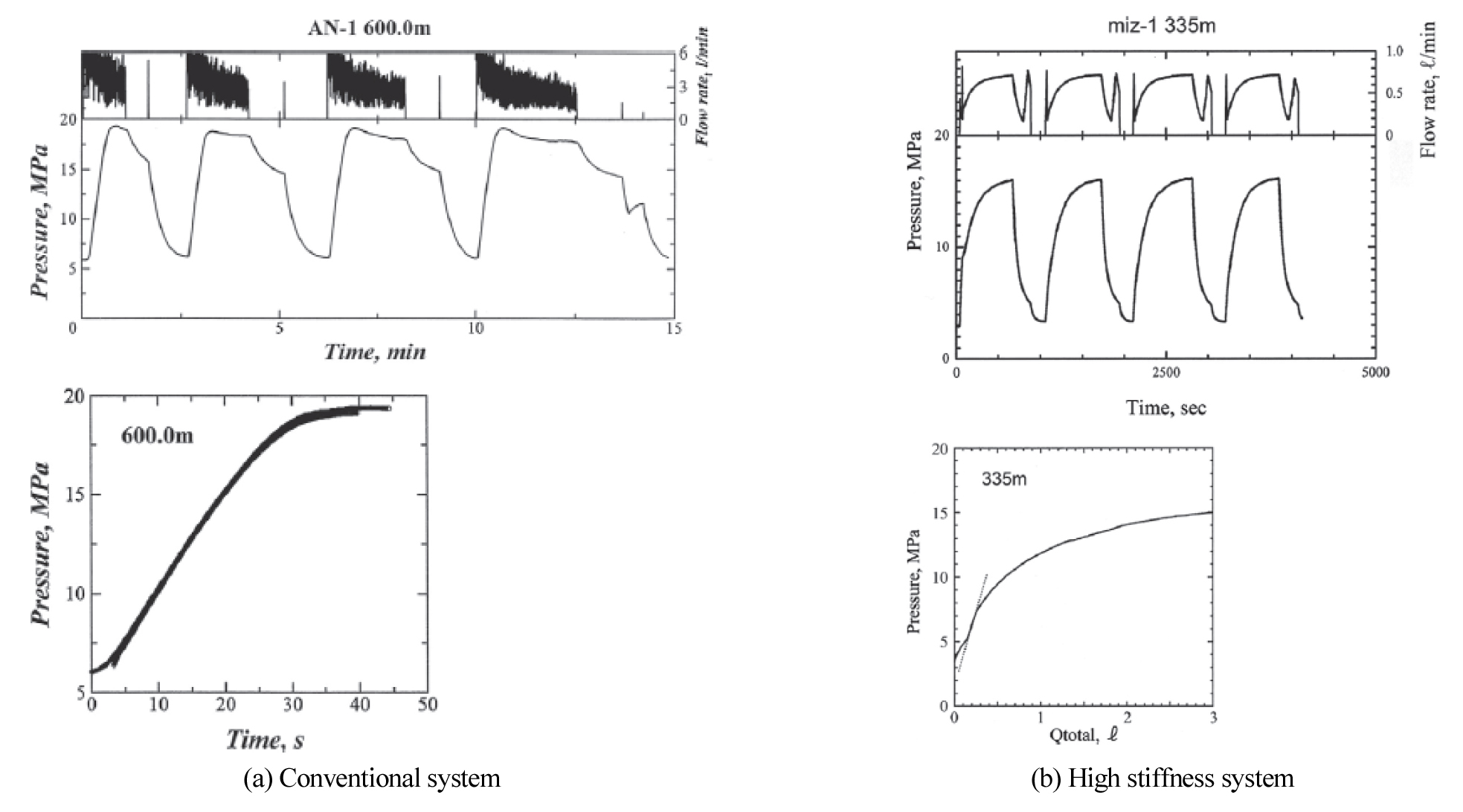
Fig. 16.
Pressure responses at two hydraulic fracturing systems with different compliances (Sato et al., 2012)
4. 결 론
초기응력은 암반 내 굴착에 기이한 응력재분배를 예측하는 데 가장 기본적인 정보로 지하구조물이 건설되는 암반의 안전성 평가를 위한 필수 요소에 해당한다. 본고에서는 시추공을 이용한 대표적인 초기응력 측정법인 수압파쇄법에 관한 일본지반공학회에서 최근 제안한 표준시험법을 검토하고 측정결과의 신뢰도 제고를 위해 고안된 기술요소들을 소개하였다.
첫째로, 수압파쇄에 의해 형성된 균열의 표면 거칠기로 인해 shut-in 이후 균열은 완전히 닫히지 않고 잔류 간극이 존재하게 된다. 이로 인해 재가압 과정에서 균열재개 시점의 균열 내 수압은 초기공극수압과 다르다는 전제로부터 균열재개압력 계산식을 수정하여 제안하였다. 둘째로, 주입유량-압력변화 거동으로부터 결정되는 균열재개압력은 수압파쇄시스템의 컴플라이언스 특성에 크게 의존하고 있어 수압파쇄로부터 획득하는 초기응력 추정치의 정밀도 제고를 위해서는 시스템 컴플라이언스를 충분히 낮게 제작해야함을 보였다. 또한, 수압파쇄시스템 컴플라이언스 기준 설정을 위해 주변 암반의 탄성계수를 달리하여 균열재개압력을 계산한 결과, 암반의 탄성계수에 비해 시스템 컴플라이언스가 충분히 낮아야함을 보였다.
국내에서도 사용후핵연료 처분장 건설을 위한 부지특성조사 등에서 수백 미터 이상 심도의 시추공을 이용한 초기응력 측정이 요구되고 있다. 수압파쇄를 이용한 국내 초기응력 측정 사례 및 해석방법에 대한 연구는 다수 보고된 바 있으나(Bae et al., 2008, Choi et al., 2008, Synn et al., 2013) 수압파쇄장치의 컴플라이언스를 분석한 연구는 미흡한 실정이다. 부지특성조사에 적용하는 수압파쇄시스템의 컴플라이언스는 조사 시추공 직경과 유사한 강성의 철 파이프 등을 이용하여 작용 수압-유량의 관계로 파악할 수 있으므로 이를 토대로 대상 부지 암반의 강성(탄성계수)을 고려한 초기 응력 측정 시스템의 적용 타당성을 사전 검토할 수 있을 것이다.
Acknowledgements
한국지질자원연구원 기본사업과 2021년도 정부(원자력안전위원회)의 재원으로 사용후핵연료관리핵심기술개발사업단 및 한국원자력안전재단의 지원(2109092-0121-WT112)을 받아 수행되었습니다. 제1저자는 2019년도 정부(과학기술정보통신부) 재원으로 한국연구재단 기초연구사업(2019R1F1A105871113)의 지원을 받았습니다. 지원에 감사드립니다.
References
Bae, S., Kim, J., Kim, J., and Lee, Y., 2008, In-situ rock stress measurment at the water tunnel sites in the OO oil storage facility with hydraulic fracturing method, Tunnel and Underground Space, 18(1), 80-89.
Choi, S., Park, C., Synn, J., and Shin, H., 2008, 10 years experience of in-situ stress measurments using a hydraulic fracturing for tunnel design, Korean Society for Rock Mechanics Spering Meeting, 79-88.
Cornet, F.H., 1986, Stress determination from hydraulic tests on preexisting fractures -the HTPF method, in Proc. Int. Symp. on Rock Stress and Rock Stress Measurements, Stockholm, Centek Publ., Lulea, Sweden, 301-312.
Cowtgill, S.M., Meredith, P.G., Murrelland, A.F., and Brereton, N.R., 1993, Crustal stresses in the North Sea from breakouts and other borehole data, in Proc. 34th US Symp. Rock Mech., Madison, Int. J. Rock Mech. Min. Sci. & Geomech Abstr., 30, 113-116.
10.1016/0148-9062(93)90079-SDe la Cruz, R.V., 1977, Jack fracturing technique of stress measurement, Rock Mech., 9, 27-42.
10.1007/BF01238568Fairhurst, C., 1964, Measurement of in situ rock stresses with particular references to hydraulic fracturing, Rock Mech. Eng. Geol., 2, 129-147.
Geertsma, J., and Klerk, F.d., 1969, A Rapid Method of Predicting Width and Extent of Hydraulically Induced Fractures, J. Pet. Tech., 21. 1571-1581.
10.2118/2458-PAHaimson, B.C., 1978, The hydro fracturing stress measuring method and recent field results, Int. J. Rock Mech. Min. Sci. & Geomech. Abstr., 15, 167-178.
10.1016/0148-9062(78)91223-8Haimson, B.C., and Lee, M.Y., 1995. Estimating in situ stress conditions from borehole breakouts and core disking - experimental results in granite, in Proc. Int. Workshop on Rock Stress Measurement at Great Depth, Tokyo, Japan, 8th ISRM Congress, 19-24.
Hickman, S.H., Healy, J.H., and Zoback, M.D., 1985, In-situ stress, natural fracture distribution, and borehole elongation in the Auburn geothermal well, J. Geophys. Res., 90, 5497-5512.
10.1029/JB090iB07p05497Hiramatsu, Y., and Oka, Y., 1968, Determination of the stress in rock unaffected by boreholes or drifts from measured strains or deformations, Int. J. Rock Mech. Min. Sci., 5, 337-353.
10.1016/0148-9062(68)90005-3Hubbert, K.M., and Willis, D.G., 1957, Mechanics of hydraulic fracturing, Petrol. Trans. AIME, T.P. 4597, 210, 153-166.
10.2118/686-GIshida, T., and Saito, T., 1995, Observation of core discing and in situ stress measurements; Stress criteria causing core discing, Rock Mech. Rock Engng, 28(3), 167-182.
10.1007/BF01020150Ito, T., and Yokoyama, T., 2021, Effec0t of system compliance on pressure-time curve at reopening and new standard in Japan, the 55th US Rock Mechanics/Geomechanics Symposium, Houston, Texas, USA 20-23, June 2021, ARMA21-2069.
Ito, T., Evans, K., Kawaiand, K., and Hayashi, K., 1999, Hydraulic fracture reopening pressure and the estimation of maximum horizontal stress, Int. J. Rock Mech. Min. Sci. & Geomech. Abst., 36, 811-826.
10.1016/S0148-9062(99)00053-4Ito, T., Igarashi, A., Ito, H., and Sano, O., 2005, Problem for the maximum stress estimation by hydrofracturing method and its potential solution, In Proc. of the 40th US Rock Mech. Symp., Anchorage, 25-29 June 2005, ARMA/USRMS 05-862.
Ito, T., Igarashi, A., Kato, H., Ito, H., and Sano, O., 2006, Crucial effect of system compliance on the maximum stress estimation in the hydrofracturing method: Theoretical considerations and field test verification, Earth Planets and Space, 58: 963-971.
10.1186/BF03352601Kaiser, J., 1953, Erkenntnisse und Folgerungen aus der messung von metallischen Werkstoffen, Arch. Eisenhutt., 24, 1/2, 43-45.
10.1002/srin.195301381Kanagawa, T. Hayashi, M., and Nakasa, H., 1977, Estimation of stress component in rocks using acoustic emission, Proc. JSCE, 258, 63-75.
10.2208/jscej1969.1977.258_63Kanagawa, T., Hayashi, M., and Hibino, S.,1975, Review of in-situ stress measurement, Proc. JSCE Symp. Rock Mech., 9, 46-49.
Kanagawa, T., Hibino, S., and Ishida, T., 1983, 3D in-situ stress measurement using over-coring method, CRIEPI Report, 385033, 1-21.
Kehle, R.O., 1964, Determination of tectonic stresses through analysis of hydraulic well fracturing, J. Geophys. Res., 69, 252-273.
10.1029/JZ069i002p00259Kobayashi, S., Yoshida, F., and Uchida, Y., 1990, Method for Initial Stress Measurement by Compact Conical-ended Borehole Strain gage, Japan Symposium on Rock Mechanics, 8, 279-284.
KSRM (Korean Society for Rock Mechanics and Rock Engineering), 2016, Standard Method for Hydraulic Fracturing of in-situ stress Measurement, http://www.ksrm.or.kr.
Leeman, E,R., 1959, The Measurement of changes in rock stress due to mining, Mine Quarry Eng., 25(7), 300-304.
Leeman, E.R., 1964, The measurement of stress in rock-Parts I, II and III, J. S. Afr. Min. Metall., 65, 45-114.
Leeman, E.R., 1968, The Determination of the complete state of stress in rock in a single borehole laboratory and underground measurements, Int. J. Rock Mech. Min. Sci., 5, 337-353.
10.1016/0148-9062(68)90021-1Matsuki, K. and Takeuchi, K.. 1993, Three-dimensional in situ stress determination by anelastic strain recovery of a rock core, in Proc. 34th US Syrup. Rock Mech., Madison, also published in Int. J. Rock Mech. Min. Sci. & Geomech. Abstr., 30, 1019-1022.
10.1016/0148-9062(93)90064-KMatsuki, K., 1989, In-situ stress measurement using DSA, Proc. Workshop on Crustal Stress Measurement, MMIJ, 92-104.
Matsuki, K., 1991, Three-dimensional in situ stress measurement with anelastic strain recovery of a rock core, in Proc. 7th Cong. Int. Soc. Rock Mech. (ISRM), Aachen, Balkema, Rotterdam, 1, 557-560.
Matsuki, K., Hongo, K., and Sakaguchi, K., 1997, The relationship between the shape of a disced core and three-diemensional in-situ stresses estimated by a tensile principal stress analysis, Journal of MMIJ, 113, 317-324.
10.2473/shigentosozai.113.317Merrill, R.H., 1967, Three component borehole deformation gage for determining the stress in rock, US Bureau of Mines Report of Investigation RI 7015.
Mizuta, Y., Sakuma, S., Katoh, H., and Kikuchi, S., 1988, Stress and stress change measurements by hydraulic fracturing and double fracturing for safe underground excavation, Proc. 2nd Int. Work Shop on Hydraulic Fracturing Stress Measurement, 205-244.
Mizuta, Y., Sano, O., Ogino, S.. and Katoh, H., 1987, Three dimensional stress determination by hydraulic fracturing for underground excavation design, Int. J. Rock Mech. Min. Sci. & Geomech. Abstr., 24, 15-29.
10.1016/0148-9062(87)91228-9Obara, Y., and Sugawara, K., 1990, Field stress measurements in jointed rock, Proc. of Int. Conf. on Mech. of Jointed and Faulted Rock, Vienna, 827-834.
10.1201/9781003078975-113Obert, L., Merrill, R.H., and Morgan, T.A., 1962, Borehole deformation gauge for determining the stress in mine rock, US Bureau of Mines Report of Investigation RI 5978.
Oka, Y., Kameoka, Y., Saito, T., and Hiramatsu, Y., 1979, Investigations on the new method of determining rock stress by the stress relief technique and applications of this method, Rock Mechanics in Japan, 3, 68-70.
Okabe, T., Shinohara, N., Takasugi, S., and Hayashi, K., 1996, Earth's crust stress field estimation by using vertical fractures caused by borehole drilling, Proc. VIII th International Symposium on the Observation of the Continental Crust Through Drilling, Tsukuba, 265-270.
Pine, R.J., Tunbridge, L.W., and Kwakwa, K., 1983, In-situ stress measurement in the Carnmenellis Granite-I. Overcoring tests at South Crofty Mine at depth of 790m, Int. J. Rock Mech. Min. Sci. & Geomech. Abstr, 20(2), 51-62.
10.1016/0148-9062(83)90327-3Plumb, R.A., and Cox, J.W., 1987, Stress directions in eastern North America determined to 4.5km from borehole elongation measurements, J. Geophys, Res., 92(B6), 4805-4816.
10.1029/JB092iB06p04805Sakaguchi, K., Obara, Y., Nakayama, T., and Sugawara K., 1992, Accuracy of rock stress measurement by means of conical-ended borehole technique, Journal of MMIJ, 108, 455-460.
10.2473/shigentosozai.108.455Sano, O., Ito, H., Hirata, A., Mizuta, Y., 2005, Review of methods of measuring stress and its variations, Bull. Earthq. Res. Inst. Univ., Tokyo, 80, 87-103.
Sano, O., Yokoyama, T., Ogawa, R., Orita, Y., Nakayama, M., Itamoto, K., and Kuwabara, Q., et al., 2007, Proc. of the 28th West Japan Symposium on Rock Engineering, 65-70.
Sato, T., Tanno, T., Hikima R., Sanada, H., and Kato, H., 2012, Data quality of in-situ stresses by hydraulic fracturing method - applicability of high-compliance system and evaluation of maximum stress based on the results in granite, Journal MMIJ, 128, 449-454.
10.2473/journalofmmij.128.449Scheidegger, A.E., 1962, Stresses in the Earth's crust as determined from hydraulic fracturing data, Geologie und Bauwesen, 27, 45-53.
Serata, S., and Kikuchi, S., 1986, A diametral deformation method for in situ stress and rock property measurement, Int. J. Min. Geol. Eng., 4, 15-38.
10.1007/BF01553754Seto, M., Utagawa, T., Kiyama, T., and Katsuyama, K., 1990, The estimation of pre-stress from AE characteristics in cyclic loading of the pre-stressed rock, Japan Symposium on Rock Mechanics, 8, 321-326.
Siegfried, R.W., and Simmons, G., 1978, Characterization of oriented cracks with differential strain analysis, J. Geophys. Res., 83, 1269-1278.
10.1029/JB083iB03p01269Simmons, G., Siegfried, R.W., and Feves, M.L., 1974, Differential strain analysis: a new method for examining cracks in rocks, J. Geophys. Res., 79, 4383-4385.
10.1029/JB079i029p04383Stephansson, O., 1983, Rock stress measurement by sleeve fracturing, in Proc. 5th Cong. Int. Soc. Rock Mech. (ISRM), Melbourne, Balkema, Rotterdam, 129-137.
Stock, J.M., Healy, J.H., Hickman, S.H., and Zoback, M.D., 1985, Hydraulic fracturing stress measurements at Yucca Mountain, Nevada and relationship to the regional stress field, J. Geophys., Res., 90(B10), 8691-9706.
10.1029/JB090iB10p08691Strickland, F.G., and Ren, N.-K., 1980, Use of differential strain curve analysis in predicting the in-situ stress state for deep wells, in Proc. 21st US Symp. Rock Mech., Rolla, University of Missouri Publ., 523-532.
Sugawara, K., and Obara,Y., 1986, Measurement of In-situ Rock Stress by Hemispherical-ended Borehole Technique, Int. J. Min. Sci. & Tech., 3, 287-300.
10.1016/S0167-9031(86)90632-8Sugawara, K., Kameoka, Y., Sito, T., Oka, Y., and Hiramatsu, Y., 1978, A study on core discing pheonomenon, Journal of MMIJ 94, 1089, 797-803.
10.2473/shigentosozai1953.94.1089_797Sugawara, K., Obara, Y., Araki, H., and Ishimura, S., 1987, Rock stress measurement using sleeve fracturing, Japan Symposium on Rock Mechanics, 7, p.181-186.
Sugawara, T., Ishijima, Y., and Ishizeki, T., 1999, Development of Rock stress measurement system by borehole deformation method, Proc. MMIJ Spring Meeting, 127-128.
Synn, J., Park, C., Kim, K., 2013, Hydraulic fracturing and 2D-3D in-situ stress analysis in jointed rock mass, Korean Society for Rock Mechanics Spring Meeting, 2013.03, 11-15.
Teufel, L.W., 1983, Determination of in-situ stress from anelastic strain recovery measurements of oriented core, Symposium on low permeability gas reservoirs, Denver, Colorado, SPE/DOE 11649, 421-430.
10.2118/11649-MSVoight, B., 1968, Determination of the virgin state of stress in the vicinity of a borehole from measurements of a partial anelastic strain tensor in drill cores, Felsmechanik und Ingenieurgeologi, 6, 201-215.
Wolter, K.E., and Berckhemer, H., 1989, Time dependent strain recovery of cores from KTB-deep drilling hole, Rock Mech. Rock Eng., 22, 273-287.
10.1007/BF01262283Yamamoto, 2000, Standard method of DRA, Fall meeting of The mining and materials processing institute of Japan, 71-76.
Yokoyama, K., 2013, Standardization and globalization of initial stress measurement techniques developed and improved in Japan, Journal of MMIJ, 129, 683-693.
10.2473/journalofmmij.129.683Yokoyama, K., and Tanaka, T., 1989, In-situ stress measurement by AE and deformation rate analysis, Japan, Applied Geological Society Conference, 5-8.
Yokoyama, K., et al., 2012, In-situ stress measurement by core discing, Proc. of MMIJ 2012 (Akita), 256-268.
Yokoyama, T., 2017, Current status and standardization of initial stress measurement techniques, Annual Report of Applied Geology, 36, 2017.
Yokoyama, T., and Nakanishi, A., 1997, A proposal of geo-stress measurement technique by plate fracturing, Proc. of the international symposium on rock stress Kumamoto, 143-148.
Yokoyama, T., Funato, A., Ito, T., Ogawa, K., and Nayuki, T., 2021, Development and application of high stiffness hydraulic fracturing systems for stress measurements corresponding to new standard in Japan, the 55th US Rock Mechanics/Geomechanics Symposium, Houston, Texas, USA 20-23, June 2021. ARMA21-1850.
Yokoyama, T., Ogawa, K., Sano, O., Hirata, A., and Mizuta, Y., 2010. Development of borehole-jack fracturing technique and in situ measurements, Rock Stress and Earthquakes, 93-100.
10.1201/b10555-15Zoback, M.D., Barton, C.A., Brudy, M., Castillo, D.A., Finkbeiner, T., Grollimund, B.R., Moos, D.B., Peka, P., Ward, C.D., and Wiprut, D.J., 2003, Determination of stress orientation and magnitude in deep wells, Int. J. Rock Mech. Min. Sci., 40, 1049-1076.
10.1016/j.ijrmms.2003.07.001Zoback, M.D., Moos, D.L., Mastin, L., and Anderson, R.N., 1985, Wellbore breakouts and in situ stress, J. Geophys Res., 90, 5523-5530.
10.1029/JB090iB07p05523

