

1. Introduction
2. Literature Review
2.1 Laser Tunnel Marker
2.2 Tunnel Face Projection Mapping
3. Pattern Projection Technique
3.1 Software Development
3.2 Equipment Requirement
3.3 Blasting pattern Drawing file specification
4. Field Application
4.1 Test Site Characterisitcs
4.2 Projection Applications and Operational Benefits
5. Discussion
5.1 Advancing Underground Construction Through Projection Mapping
5.2 Technical and Operational Benefits
5.3 Comparative Evaluation of Projection Alignment Strategies
5.4 Limitations and Implementation Challenges
5.5 Future Research and Development
6. Conclusion
7. Code availability and Reproducibility
1. Introduction
Blasting is one of the most widely used methods for excavation in tunnel engineering, which involves several separate steps that each sequence needs to be executed accurately to avoid delays and ensure the excavation rate is maintained (Brem and Gattermann, 2006, Rana et al., 2025), and parallel execution of tasks is unfeasible (Girmscheid and Schexnayder, 2002). The only practical strategy for enhancing the excavation rate is to minimize the time-intensive nature of tasks. This approach is particularly critical for long tunnel projects, where optimizing excavation sequence durations can result in significant time savings and cost reductions, ultimately providing considerable advantages in project delivery and efficiency (Zare and Bruland, 2007, Rodríguez Alza et al., 2024).
The initial step in tunnel blasting is to design a blasting pattern tailored to the geotechnical conditions and rock mass strength of the tunnel face, which is critical, influencing both efficiency and safety (Jin et al., 2024, Liu et al., 2024). Numerous investigations demonstrate that accurate designing of blasting patterns is crucial for enhancing excavation rate and minimizing issues such as overbreak (to prevent extra amounts of shotcrete and concrete lining) and underbreak (to prevent delays caused by tunnel scaling stage), and optimizing rock fragmentation (Mei et al., 2021, Kumar et al., 2023). But not only design, but also precise execution of the designed blasting plan is crucial to ensure optimal outcomes in drilling and blasting (Ganster, 2022). Application of advanced measurement tools in blasting pattern implementation, although not explicitly mentioned in the literature, can play a crucial role in enhancing the precision of excavation and progress rate.
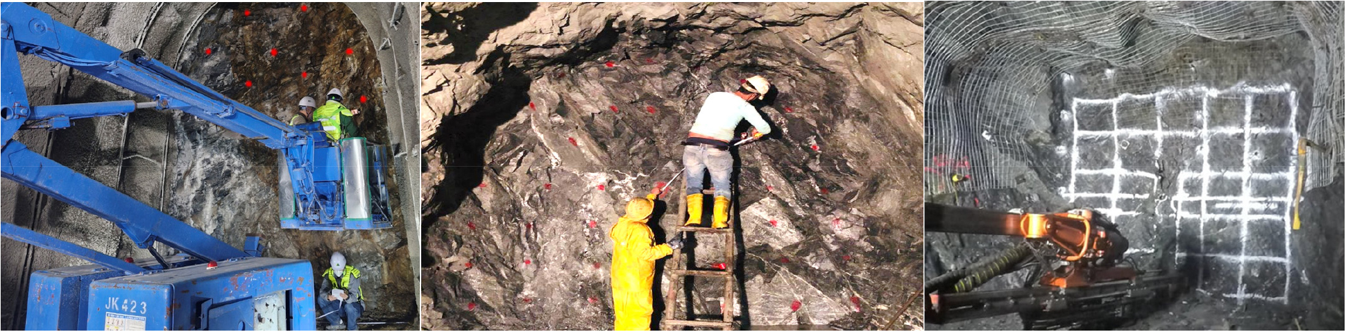
Traditionally, drawing or marking blasting patterns on the tunnel face was done manually using tools like measuring tapes, bars, and strings (Fig. 1). However, this method was labor-intensive, time-consuming, and often led to inaccuracies, resulting in efficiency issues. During the past years, total-station and laser-based systems have emerged as solutions to enhance the precision and speed of tunnel survey processes. However, despite their high accuracy, these systems are still very time-consuming to set up and necessitate expert manpower to operate.
Any development of innovative methods for speeding up tunnel drilling and blasting sequences is crucial in the underground construction industry, particularly in the context of increasing automation and labor-saving needs. The projection mapping technique is an innovative solution that aims to optimize blasting operations by providing detailed visual surveying information about the rock mass properties, drilling plan, and detailed information of explosive charges and detonators, directly on the tunnel face. Thereby reducing errors and improving safety, enhancing operational efficiency and accuracy, and addressing longstanding challenges in the field.
This paper introduces a simple pattern projection system that enables projecting any visual information on tunnel faces quickly and accurately without the need for any special advanced equipment or professional expertise, with only ordinary light beam projectors. This system facilitates rapid and accurate implementation of designed plans in the field, optimal placement of explosives following visual projected information, speeding up the surveying process, and finally increasing excavation rate and reducing overbreak and underbreak incidents.
2. Literature Review
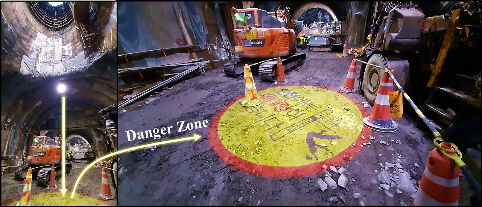
One of the most common applications of projectors in the construction industry, as shown in Fig. 2, is to highlight hazardous zones by projecting warning signs onto specific areas, thereby informing workers of potential dangers and enhancing safety without the need for physical barriers. However, projection technology holds greater potential to further improve efficiency, accuracy, and safety in construction tasks. In particular, the integration of advanced measurement systems aims to enhance the precision of marking critical points in tunnel construction. Tunnel face pattern projection mapping has emerged as an innovative approach in modern tunneling, supporting activities such as the accurate positioning of steel supports, rock bolts, and drill holes for blasting operations.
2.1 Laser Tunnel Marker
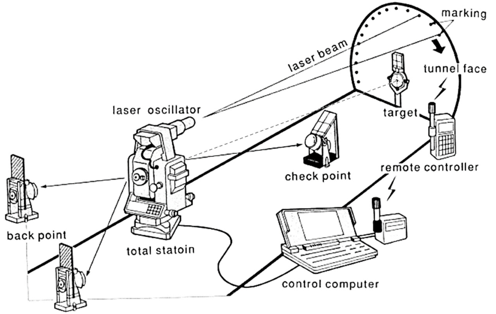
Tunnel projection mapping or face marking system, named tunnel marker, was innovated for the first time in Japan (Murakami and Yamazaki, 1992). As schematically illustrated in Fig. 3, this system incorporates a laser projector, total station, tripod, two reflecting mirrors, and a survey computing unit to accomplish the following tasks:
∙ Display the tunnel center and centerline
∙ Show steel support assembly positions
∙ Present peripheral lines for excavation cross-sections
∙ Indicate positions for side and relief holes for blasting
The tunnel marker system enhances marking accuracy and speed, offering a significant improvement over traditional manual methods. But this system had some limitations. The most important limitation was that the system employs laser beam projectors, which raises two problems. The first problem was that the laser projected patterns are difficult to recognize in short projection distances (less than 30 m), particularly on uneven tunnel faces. Then it is suitable for the situations where the projector could be installed around 100 meters away from the tunnel face, where in this case the laser beam can be intercepted by ventilation ducts or other obstacles before reaching the tunnel face, which can affect the accuracy and efficiency of the marking process. The second problem is that directly looking into a laser beam in dark underground spaces can cause severe eye injuries or permanent blindness danger to workers. Finally, despite the automation, the system still requires manual adjustments and checks to ensure accuracy, such as fixing device positions, control of the total station and projector for effective operation, and it needs to employ expert surveyors.
2.2 Tunnel Face Projection Mapping
The technology was developed to project ground information, such as images of the tunnel face and rock strength data, directly onto a shotcrete tunnel face. This system was designed for ease of use and safety, eliminating the need for extra surveying work, which is challenging in tunnel environments. This technique has been recently developed further by advancing high-power compact projectors. These projectors are able to provide very bright and clear images from distances close to the tunnel face (Tani et al., 2023).
The technology relies heavily on a specific set of high-end components: projectors with laser light sources, a protective dust- and drip-proof case, and a robust control panel integrated into a specialized drill jumbo (Fig. 4). The technology is operated using simple push buttons on the drill jumbo, allowing workers to project images without complex interactions. By projecting relevant data onto the tunnel face, the system helps determine appropriate quantities of explosives according to rock mass strength, reducing the need for extra shotcreting and preventing damage to construction equipment from flying rocks. This contributes to improved construction efficiency and safety. The system automates data acquisition and image generation by integrating sensor data from the hydraulic control system and using pre-shotcreted images from a file server.
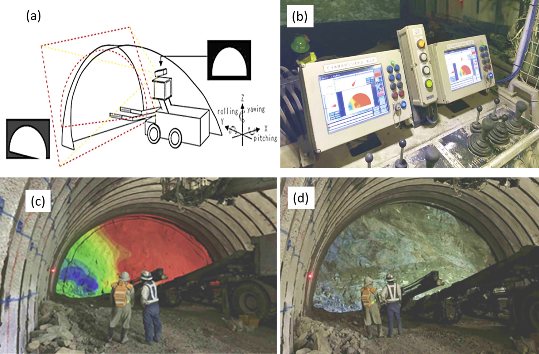
Fig. 4.
System functionalities of face projection mapping: (a) Automatic tunnel-face sensing and projection correction. (b) Rock mass strength contour obtained via measured drilling energy. (c) Color contour projected onto the tunnel face to show the distribution of hard/soft rock. (d) Tunnel face rocks image projected on the shotcrete tunnel face (Tani et al., 2023)
Despite its advantages, the system may face challenges such as: Because of the specialized hardware, replicating or adapting the system for other settings requires significant re-engineering. Therefore, the solution application is limited. If the equipment setup or the relative positions vary significantly from the designed scenario, the correction might fail to produce an accurate projection. This sensitivity to exact spatial relationships suggests that the solution may not be easily generalized to other construction environments or even different tunnel geometries. In addition, the current system only focuses on visualizing the appearance (rock textures and layers) and strength of the tunnel face (and color contour diagrams).
While this system is a major step forward for improving blasting accuracy, it stops short of full automation, particularly in automatically setting the blasting pattern and the explosive amounts. These points highlight that while the technology brings significant improvements specific to its intended environment, its adaptation to different contexts faces multiple challenges related to environmental specificity, reliance on specialized equipment, and the rigidity of its automation processes.
3. Pattern Projection Technique
3.1 Software Development
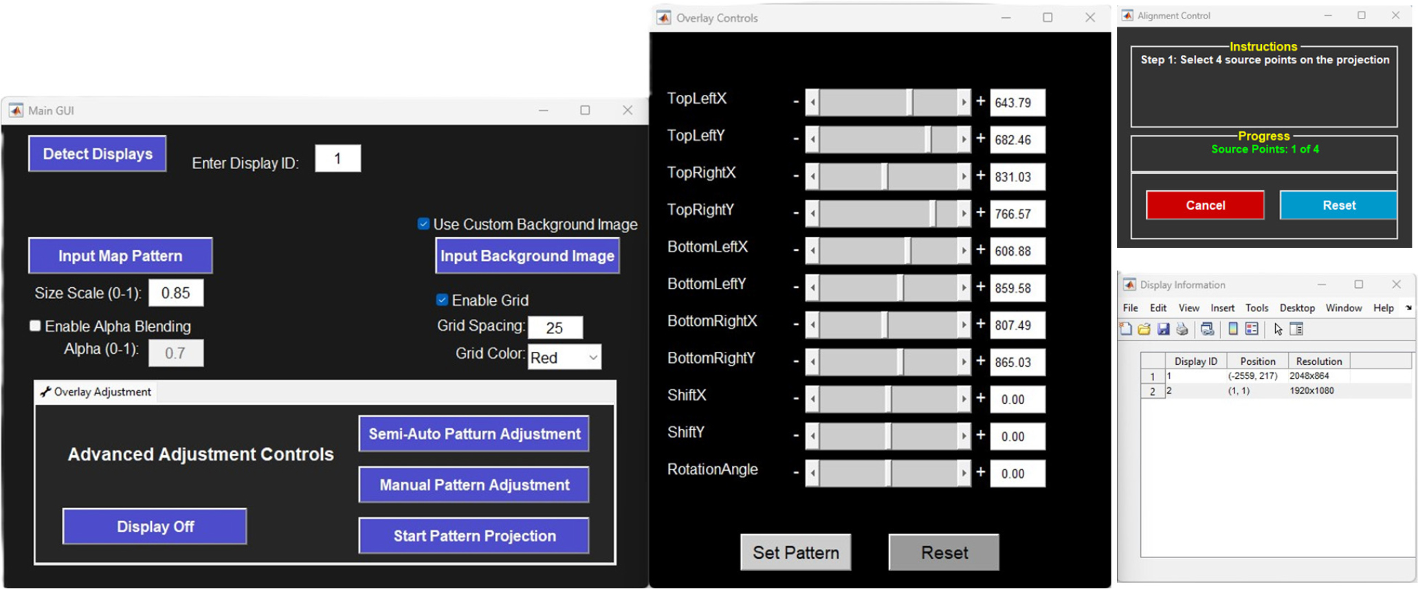
The tunnel face blasting pattern projection software presented in this paper offers a sophisticated solution for accurately transferring designed blasting patterns onto tunnel faces. This MATLAB-based graphical user interface (GUI) application (Fig. 5) enables users to upload pre-designed blasting patterns as images or animations and project them precisely onto physical tunnel surfaces. The software features a comprehensive set of tools for projector activation, pattern adjustment, and visualization, including both manual and semi-automated pattern positioning capabilities. Users can customize the projection with options such as alpha blending, scale factor, background image integration, and grid overlays to enhance visibility and accuracy. The application’s dual-display support allows for real-time pattern adjustments on a laptop screen, while simultaneously projecting onto the tunnel face.
3.1.1 Manual projection pattern alignment
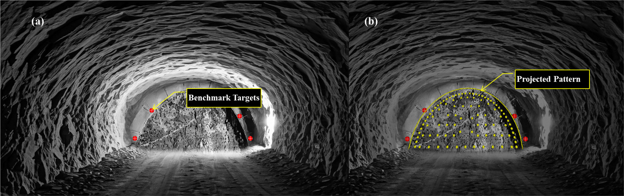
The software implements a manual pattern adjustment and enables precise alignment of blasting patterns to tunnel faces. This functionality is particularly valuable when benchmark points exist on the tunnel surface that need to be matched with corresponding points on the digital pattern. Fig. 6 (a), demonstrates an example of a tunnel face with attached markers, and b, illustrates the results of manual adjustments and blasting pattern projection. While this manual approach requires more time, it provides superior control over the final projection alignment.
The function creates a dual-display system: the pattern is projected onto the tunnel face via a projector, while a control interface is displayed on the primary monitor (Laptop screen). The system creates a full-screen projection window. The blasting pattern is initially positioned using default values or previously saved parameters, applying appropriate scaling and positioning based on the projector’s display dimensions. The core of the adjustment mechanism employs a projective transformation that allows for precise manipulation of the pattern’s four corners independently. This approach enables the operator to adjust for perspective distortion, irregular tunnel surfaces, and varying projection angles. The control interface features eleven separate sliders for fine-tuning the pattern position, including individual X-Y coordinates for each corner, global X-Y positioning shifts, and rotation angle adjustment (Fig. 5). These parameters are dynamically updated in real-time as adjustments are made, immediately reflecting changes on the projected image. In addition, the system’s interactive capabilities are enhanced by draggable corner markers directly on the projection display. These markers can be manually positioned to align with physical benchmark points on the tunnel face, allowing for intuitive pattern adjustment without relying solely on numerical inputs. Alpha blending and background capabilities are also implemented to enhance visibility by controlling the transparency and sharpening contrast between the pattern and the tunnel face, which is particularly useful in varying lighting conditions.
3.1.2 Automatic projection pattern alignment
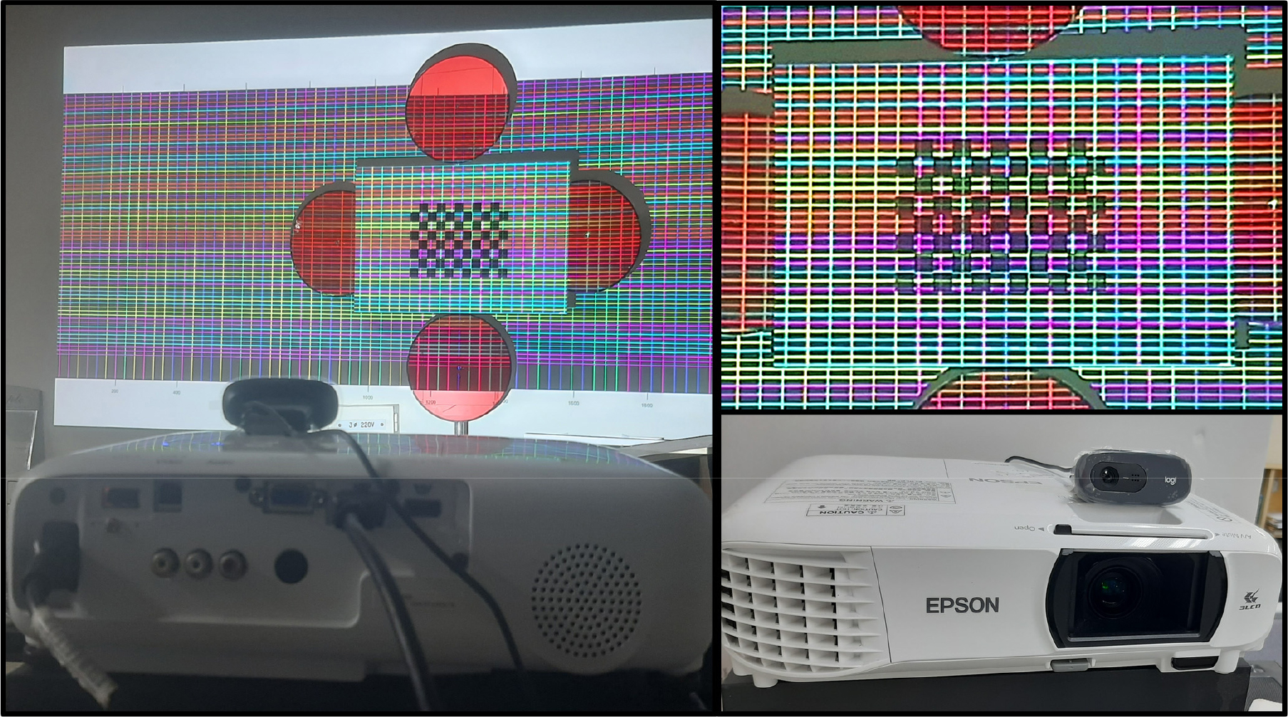
For this research, we tried to implement a standard Webcam-Projector calibration approach to make the pattern projection process fully automatic. Using open-source tools (OpenCV), along with the MATLAB code from Huang et al. (2021), we first calibrated the camera, then used structured-light patterns to establish camera-projector correspondences. This allowed us to determine the projector/camera intrinsics and extrinsics parameters and alignment factors. Our lab tests showed this method achieves pixel accuracy, enabling precise alignment between projected imagery and physical features captured beforehand. Fig. 7 shows our camera-projector-target test setup. This is called a single-shot projector-camera calibration technique that works well for systems needing frequent recalibration (Huang et al., 2021). This approach combines a structured light pattern with a standard checkerboard to uniquely identify key points in the projected pattern. A graph-theory algorithm establishes correspondences between camera and projector images, which helps align the projected pattern with the actual scene. The availability of open-source code made implementation much easier (Github.com).
In this research, we found that while the system doesn’t need recalibration when changing the distance to the projection surface (as long as the camera-projector setup remains fixed), we still need to estimate the new surface’s pose for accurate alignment. This creates practical problems in real-world applications. The method works fine in lab settings with detectable planar features, known markers, or uniform surfaces. But it struggles in underground tunnels where surfaces are irregular, lighting is poor, and environmental factors make reliable pose estimation difficult. These limitations prompted us to develop another simple and fast semi-automatic alternative approach for tunnel environments.
3.1.3 Semi-automatic projection pattern alignment
The semi-automatic alignment system enables real-time interaction, and the user interacts with a graphical control interface to define correspondence points between the projected pattern and desired target locations. After picking target points, the software computes an optimal projective transformation based on these correspondences. The transformed pattern is then projected with optimized positioning that compensates for surface irregularities and projection angles. The alignment process follows a structured two-step approach:
Step 1: Aligning point selection
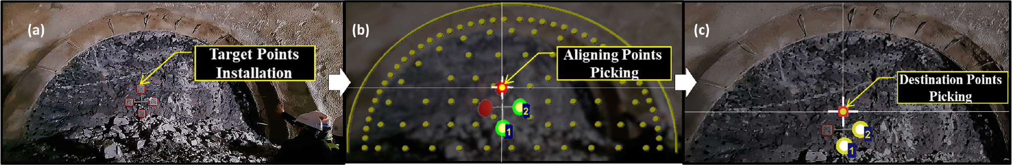
The user identifies and selects four distinct points on the designed pattern. These source points serve as tie points that will be mapped to the reference markers. Reference markers could be placed on a pre-designed, known scale bar fixed and georeferenced on the tunnel face using surveying techniques (Fig. 8 (a)). For visibility in underground environments, the point picking process is facilitated with a high-contrast white cross sign with a green circle and sequential numbering for picked points (Fig. 8 (b)).
Step 2: Destination point selection
After defining the aligning points, the user selects the corresponding destination positions where these points should appear in the final projection. These points are marked in yellow to distinguish them from the source points, maintaining clarity throughout the process (Fig. 8 (c)).
Once all points have been defined, the system automatically calculates a homography matrix. This transformation maps the source coordinates to their corresponding destination positions, effectively creating a customized projection. The calculated parameters are then saved for rapid redeployment of the high-resolution blasting pattern, rock mass strength contour map, or any other projectable useful pictures or information. This semi-automatic approach significantly improves the speed and accuracy of blasting pattern projection compared to fully manual methods, while providing greater reliability than fully automatic systems in challenging tunnel environments. The interactive nature of the process allows for immediate verification and adjustment, ensuring optimal pattern placement.
3.2 Equipment Requirement
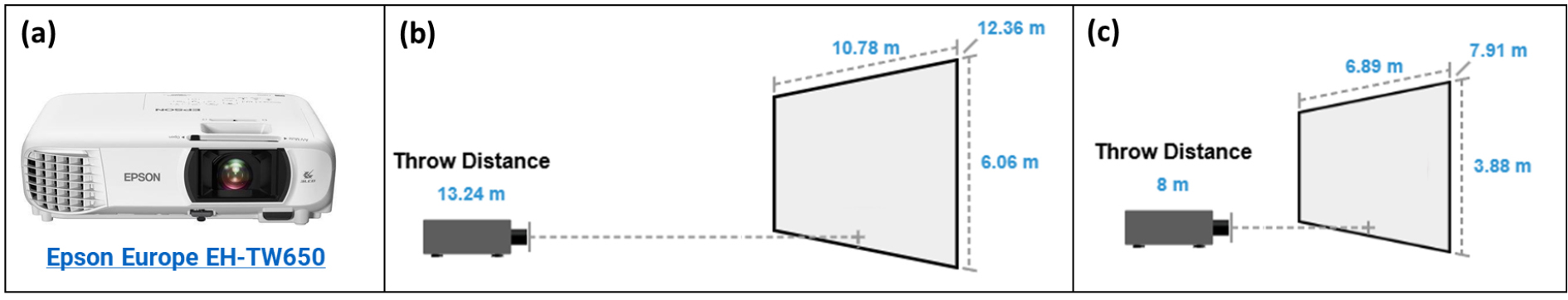
For this research implementation, we utilized an Epson EH-TW650 projector (Fig. 9 (a)) featuring 1920×1080 resolution and a maximum throw distance capability of 13.2 meters, which can theoretically cover an area exceeding 60 m2 (Fig. 9 (b)). While this projector is primarily designed for indoor office environments rather than outdoor large-scale applications, it proved adequate for our development purposes, given the available resources. Since our target research tunnel face has a smaller surface area, we optimized the setup by reducing the throw distance to approximately 8 meters. At this reduced distance, the projector effectively covers a surface area of over 28 m2 while maintaining high image brightness in the low-light conditions typical of underground environments (Fig. 9 (c)).
A significant challenge in tunnel projection applications involves the optical properties of rock surfaces, which are characteristically dark and uneven. These surfaces typically exhibit low screen gain values (generally below 1.0), resulting in reduced image brightness on the projected surface. When selecting appropriate projection equipment for tunnel blasting pattern applications, two critical factors must be considered: the dimensions of the tunnel face and the optical properties of the target surface (with screen gain conservatively estimated at 1.0 for calculation purposes).
The market currently offers numerous projector models with varying lens configurations and brightness specifications suitable for different application requirements. For permanent or professional implementation of this technology, specialized projectors designed for large-format projection in challenging environments would be more appropriate. It is worth noting that recent advances in projection technology have produced units capable of covering extensive areas even at relatively short throw distances, which could significantly enhance implementation flexibility in limited tunnel spaces.
3.3 Blasting pattern Drawing file specification
The preparation of blasting patterns for projection onto tunnel surfaces necessitates adherence to specific file creation protocols. Each blasting design must be generated at actual scale dimensions and maintained in two distinct file versions: one incorporating reference target points and another containing only the pure pattern design. This dual-file approach facilitates a two-phase implementation process. Initially, the reference-point version enables precise geometric calibration and transformation matrix parameter adjustment to align the virtual pattern with the physical tunnel face. Subsequently, the calibrated projection system displays the high-resolution clean pattern version, providing unobstructed visualization of the drilling locations. The projection software developed in this research supports two image formats (JPG, PNG) for static pattern projection and video formats (MP4, GIF) for dynamic visualization applications, offering flexibility for various blasting design visualization requirements.
4. Field Application
4.1 Test Site Characterisitcs
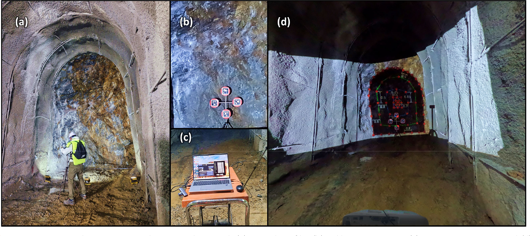
Field validation of the developed projection methodology was conducted at the Hyundai Research Tunnel located in South Korea. This underground laboratory was specifically designed and constructed to facilitate research on advanced technology applications in tunneling operations, making it an ideal environment for evaluating the performance of the projection system in real underground conditions. The test tunnel has been excavated in metamorphic rock formations predominantly comprised of gneiss and altered granite. The excavated cross-section measures 3.5 meters in width and 5 meters in height after installation of the support system. Fig. 10 illustrates the experimental setup: (a) the research tunnel profile, (b) reference targets installed on the tunnel face for alignment calibration, (c) the integrated computer-projector system configuration, and (d) preliminary calibration tests conducted to optimize throw distance, projection area coverage, and image brightness on uneven tunnel face.
4.2 Projection Applications and Operational Benefits
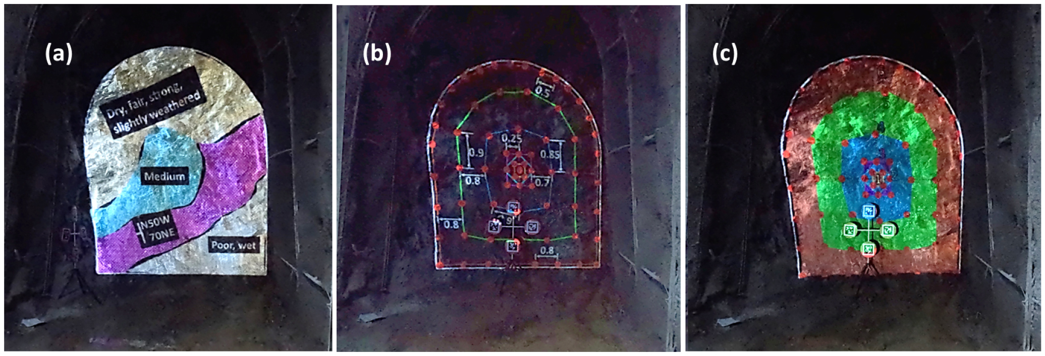
The projection system demonstrated exceptional versatility in visualizing multiple categories of critical information directly onto the tunnel face. Fig. 11 showcases three primary application scenarios: (a) geotechnical information overlay displaying rock mass characteristics and rock mass strength contour mapping, (b) precise drilling pattern visualization with hole locations and angles, including annotations, and (c) blast design parameters including explosives placement configurations and detonator delay sequencing for optimized sequential cutting.
This direct visualization methodology offers substantial operational advantages over conventional approaches. The system enables drilling technicians to observe design specifications in situ with high spatial accuracy, eliminating the need for manual face marking, which is always time-consuming and associated with access difficulties and dangers. Implementation of this technology yielded measurable improvements in several operational domains:
∙ Significant reduction in time required for pattern layout and drill positioning
∙ Decreased incidence of drill hole positioning errors and misaligned blastholes
∙ Enhanced ability for on-site engineers to make real-time adjustments based on actual conditions observed at the tunnel face
∙ Reduced cognitive load on operators working in challenging underground environments with limited visibility and access constraints
The field application confirmed that the projection system effectively bridges the gap between digital design and physical implementation in underground excavation operations, demonstrating particular value in complex tunnel excavation scenarios requiring precise execution of blasting patterns.
5. Discussion
5.1 Advancing Underground Construction Through Projection Mapping
Literature review demonstrates that projection mapping extends well in underground excavation. Its potential uses include blasting optimization, support system installation, geological mapping, and construction quality control. These applications suggest that projection mapping may become a cornerstone technology in the ongoing digital transformation of underground construction, enhancing both safety and operational efficiency in complex subsurface environments. A key capacity of the application of pattern projection systems is to reduce drilling errors and misalignment of blastholes, with downstream benefits including minimized overbreak and improved fragmentation. These factors, as highlighted by Kumar et al. (2023), are critical to optimizing project economics by reducing support material usage and shortening excavation cycles.
The tunnel face projection approach offers several advantages that represent a step change from conventional practices:
∙ Enhanced Spatial Visualization: Projecting critical data (e.g., geological features, drill patterns) directly onto the tunnel face facilitates intuitive decision-making, contextualizing information in situ rather than through abstract plans or digital screens.
∙ Improved Worker Safety: Hazardous features and operational instructions can be clearly highlighted, minimizing the need for verbal communication and reducing errors due to misinterpretation or poor visibility.
∙ Operational Flexibility: Projection updates can be implemented in real-time in response to unexpected geological conditions, allowing for adaptive planning without requiring manual remarking.
∙ Increased Drilling Accuracy: Field observations confirm enhanced blasting performance, with more precise explosive use, minimized flyrock incidents, and reduced shotcrete overuse.
5.2 Technical and Operational Benefits
Compared with earlier systems (e.g., Murakami and Yamazaki, 1992, Tani et al., 2023), the proposed projection mapping system offers several key improvements:
∙ Hardware Independence: Unlike systems requiring integration with specific drilling equipment or laser devices, this solution utilizes standard projection equipment hardware, increasing accessibility for small- to mid-scale tunneling projects.
∙ Safety Enhancements: It avoids the eye safety risks associated with laser-based systems and reduces personnel exposure to hazardous environments through less manual face marking.
∙ Integrated Data Presentation: The overlay of multiple data types onto a single physical surface creates an intuitive decision-support platform for both engineers and operators.
∙ Robust Performance: The method performs reliably across diverse tunnel geometries and rock conditions, without requiring frequent recalibration or special surface preparation.
5.3 Comparative Evaluation of Projection Alignment Strategies
This study compared three projected pattern alignment methodologies: manual, automatic, and semi-automatic. The manual method provides maximum control but is time-consuming and operator-dependent. The automatic approach, while theoretically optimal, proved less reliable in field conditions due to surface variability and sensitivity to lighting and calibration drift. The semi-automatic method strikes a practical balance, combining automation with human oversight to maintain precision in variable conditions. In addition, the semi-automatic approach, potentially supplemented by manual fine-tuning, emerges as the most effective method for precision blasting
5.4 Limitations and Implementation Challenges
While the projection mapping system demonstrates notable advantages in tunnel excavation applications, several limitations and challenges were encountered during its development and field testing. A primary constraint relates to projection visibility under typical underground conditions. The dark, irregular surfaces of tunnel faces substantially reduce image clarity and contrast, limiting the effectiveness of standard projection equipment. Although the system achieved acceptable performance in controlled environments, optimal functionality in diverse underground settings would likely require the adoption of high-brightness projectors specifically designed for low-gain, high-absorption surfaces commonly found in tunneling contexts.
Highly uneven or complex topographies affect the precision of pattern alignments, potentially reducing the effectiveness of the system. Furthermore, although the system operates independently of other tunnel machinery and does not require integration with specialized drilling hardware, its successful deployment still depends on alignment with broader excavation workflows. Seamless integration with existing design, surveying, and drilling operations is essential for maximizing operational efficiency and ensuring consistent projection accuracy. Finally, implementation success may be influenced by personnel’s familiarity with digital tools. Addressing these challenges presents both a barrier and an opportunity for future development, particularly in the design of ruggedized, user-friendly systems capable of withstanding the demanding conditions typical of underground construction environments.
5.5 Future Research and Development
Building on the current findings, several promising directions are identified:
∙ Developing rugged, glove-operable integrated systems optimized for underground use.
∙ Introducing artificial texture projections on low-feature rock faces to support improved photogrammetry and digital surface modeling.
∙ Transitioning from projection to wearable AR could enable individualized guidance while overcoming limitations of surface-based display visibility.
∙ Enabling projection of pre-blast designs onto post-blast surfaces to facilitate automated quality assessments.
∙ Supporting off-site remote control and monitoring aligns with industry moves toward automation and personnel safety in hazardous environments.
∙ Transitioning from projection to wearable AR could enable individualized guidance while overcoming limitations of surface-based display visibility.
Among the above-mentioned potential future developments, implementing an AR-based system could be the most practical and impactful next step. It can build on the foundation of the current projection-based approach. The existing system has already proven the feasibility of visualizing drilling patterns directly in underground environments, and it makes the AR integration a logical progression. AR technology could address challenges of the current projection method, such as irregular rock surfaces, low light, dusty environments, and restricted viewing angles. By using smart glasses or AR headsets, operators could access personalized, heads-up displays that deliver real-time drilling guidance directly within their field of view. This would allow them to maintain natural head movements and spatial awareness while benefiting from dynamic overlays of drilling patterns. Particularly, the spatial positioning principles established in this work can be seamlessly applied to AR applications, establishing the current system as a critical precursor to this technological evolution.
6. Conclusion
This research presents a semi-automatic pattern projection system as a practical and effective solution for improving the precision and efficiency of tunnel face blasting operations. The developed methodology successfully addresses a critical gap in tunneling practice: the accurate translation of designed blasting patterns to physical implementation in challenging underground environments. By enabling the direct visualization of drilling patterns, geological information, and blast design parameters on tunnel faces, the system can significantly enhance operational workflow and excavation outcomes.
These advantages directly address industry concerns regarding excavation efficiency, project economics, and construction safety highlighted throughout the literature. Unlike previous projection systems that required specialized hardware integration or posed safety risks, our approach utilizes standard projection equipment and incorporates user-friendly interface elements.
As the underground construction industry continues to embrace digital transformation, practical visualization technologies like the pattern projection system presented here will play an increasingly vital role in bridging the gap between digital design and physical execution. By making advanced projection capabilities accessible without requiring extensive investment in specialized equipment or expertise, this research contributes to the broader goal of improving tunneling productivity, safety, and quality outcomes across a wide range of project contexts. Future work should focus on further streamlining the system’s integration with established tunneling workflows and enhancing its adaptability to diverse geological conditions and excavation challenges.
7. Code availability and Reproducibility
The complete source code is available at GitHub (https://github.com/ahmadmehri/Tunnel-Pattern-Projection-Software). The code developed by MATLAB R2023b and the implementation requires the Image Processing Toolbox (v11.1 or later). A stand-alone .exe format of the application is also included to enable users to install and use it (only on Windows operating systems).
